Wednesday, July 23, 2014

29A-08 map box installation

Putting together the map box was straightforward.  The only tweaking I had to do concerned the opening of the door.  It only opened about 75° or so.  I used the scotch bright wheel to remove just a touch of material at the bottom of the door until it opened a full 90°.  The door opening is now limited by the piano hinge, so I stopped there.


IMG 3465

Map Box


IMG 3466

Map Box, door open

Tuesday, July 22, 2014

29A-09 center panel prep

A very simple page, just counter sink holes for the center panel and install two nut plates.  I did this page right after I did the countersinking for the right panel since I had all of the tooling set up.


IMG 3462

Center Panel

29A-07 map box prep

This page was pretty straightforward preparation of parts.   The map box is a standard sub kit that appears to be used on all of the RV’s.  The only problem that I had was that it assumes that you are using driven rivets.  I’m not.  Check out one of my first postings about the tool box that called out for using driven rivets.  I hemmed and hawed and fidgeted before I realized that I wanted to learn how to use pulled rivets, not driven rivets and so I substituted LP4-3’s for AN426’s.  Same here.  I used regular LP4-3’s most places and CS4-4’s where the door closes flush against the door.  

IMG 3460

Map Box parts

29A-06 Upper Fuselage Skin

IMG 3453

Oil Reservoir & Battery Bracket 

I wonder where the battery is going to go.  It looks like it rides on top of that bracket, but I would have put it lower (on the shelf).  Let’s find out in a few weeks (probably months, but who’s counting?)  The little bit of blue is tape over the fuel return nipple (to keep out debris.)  The two bolts are where the gascolator will be re-attached sometime in the future.


IMG 3456

Upper Fuselage Skin 

That makes a big difference in appearance!  Having the upper skin in place adds another bit of visual confirmation that this is indeed becoming an airplane.  On the other hand, I really wish I had a working electric screwdriver!


IMG 3457

lateral view of Upper Fuselage Skin 

Monday, July 21, 2014

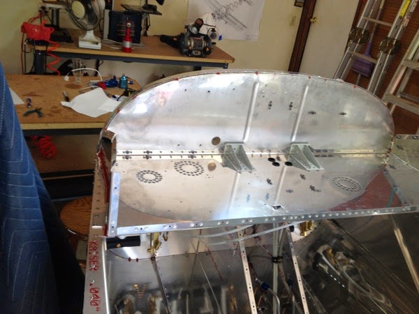
29A-05 Canopy Ribs & Panel Deck

Well, I’m back, figuratively and literally.  I’ve had a couple of vacation trips, so I was physically out of town twice for about a week each. I was also “out” motivationally.  I really hit a wall when the fuel system didn’t work and I found that I just had no motivation to work in the garage. Then I had  the fiasco of mistakenly countersinking the wrong side of not one, but two, parts.  That really put me in a funk. Anyway, i got my mojo back and found myself ready to go back to work.  Hurray!


IMG 3449

Canopy Ribs with nut plates  


IMG 3450

Canopy Ribs in place

 There was a 3rd hole in the F-1202B Panel Base that isn’t called out in the plans.  I put a snap grommet into it just on general principles that it looks better.  I’m pretty sure that there’ll be something going through it when I pull the wiring harness.

IMG 3451

Close up of Canopy Rib with RTV sealant


Monday, July 7, 2014

fuel leak at transducer

OK, I finally got the correct reducer and was able to plumb the ‘short circuit’ that would let me run the fuel pump and start looking for leaks.  I had a pretty big leak at the bottom of the tank, but I chose not to use any sealant for the temporary connection, so I’m expecting that.  


IMG 3361

Short Circuit of Fuel Supply to Fuel Return Line

What I didn’t expect is no flow at all through the circuit.  Nothing.  Nada.  Zippo. Ничего.  Nothing in the gascolator, no dribble or drainage from the fuel return line at the filler neck in the tank.    Aha!  Open the fuel cut-off valve!  Still nothing.  Wait, there’s something—a leak from the input port of the Red Cube fuel flow transducer.   I shut things down and cleaned up the mess.  When I get back from vacation, I’ll pull the red cube and see if I did something stupid like leave a protective cap inside.


Thursday, July 3, 2014

trial fit of fuel tank

well, I bet you thought I died or something.  No, but I’ve been on vacation and/or working my tail off to catch up on the vacation hours.  Today’s posting isn’t typical: it’s not a page completion but it is a milestone worth commenting on.  I’ve been worried about my fuel lines ever since EAA Tech inspection #2.  The inspector commented that I might have some leaks since I didn’t buff the edges of my flared tubes.  Rather than barging ahead, I’ve been planning on doing some leak testing before I bury the fuel lines in wiring harnesses and flight control linkages.  

Yesterday, I was finally successful in installing the fuel tank.  I couldn’t get the thing in there until I realized that there was a cleco inside the fuselage that was obstructing a good fit.  Clearing that up made all the difference in the world.

The main fuel line was amazingly close to the nipple on the bottom of the tank and was actually “easy” to attach, once I figured out that I had to get under the plane and reach up through the access holes.  (How’s that for a “duh!” moment?)  The fuel return line?  Not so much.  It was at least 1.5” too high and about the same distance too forward.  I cut & re-flared the tube to address the first issue.  I finally had a Light Bulb Moment and loosened up all of the clamps and was able to rotate the aft clamp (which is oriented transversely) and that moved the fuel return line aft very nicely.

Below, you can see the two lines attached to the bottom of the tank.  Up front, I fashioned a couple of quick lines to “short circuit” the fuel circuit, only to discover I had the wrong size reducer.  AN819 reducer’s are specified as the larger size, not the smaller size.  When the proper AN819-6D (to 4D) reducer arrives, I’ll connect the two and put a gallon of gas in the tank and run the pump.  I expect leaks at the tank, since I didn’t use any sealant, as well as at the “short circuit” in the front.  Everywhere else should better be dry!


IMG 0008 2

Fuel Line & Return Line on bottom of Fuel Tank