Saturday, January 31, 2015

46-04, Engine Prep, con't

IMG 3993

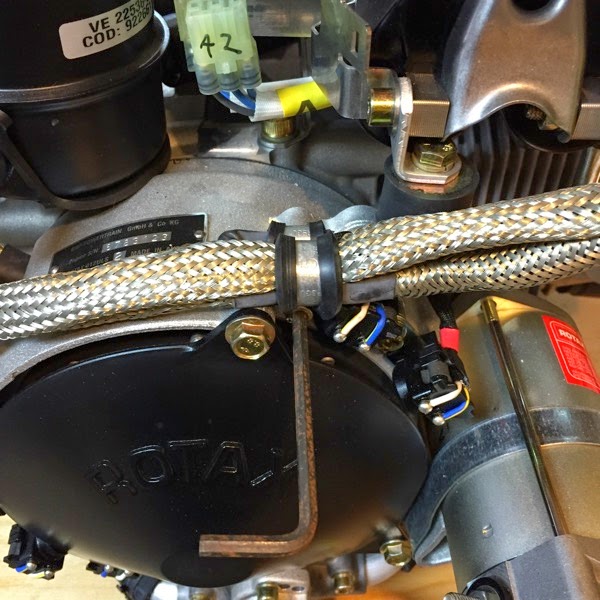
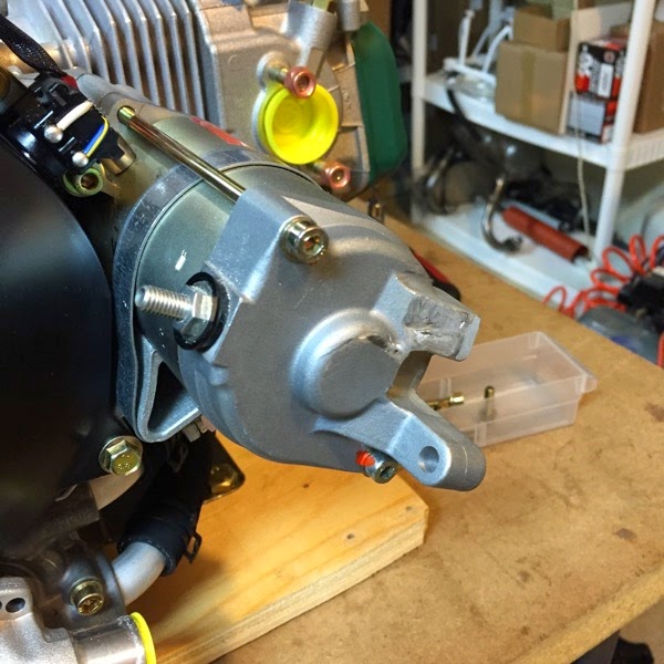
amputated starting lug

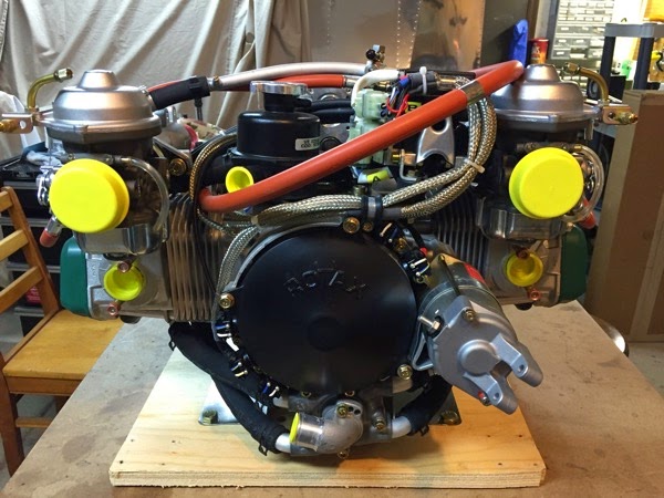
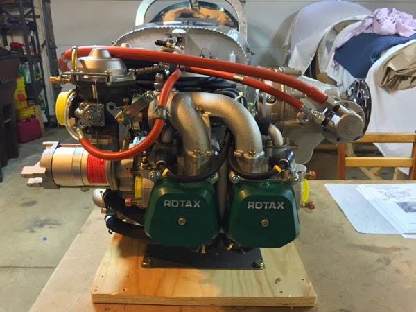
The upper lug on the starter motor gets cut off with a hack saw.  I actually cheated a bit on this step and performed it before I opened up the cylinders by removing the cooling hoses & intake manifolds.  I have tape over the open holes, but I figured having that tape wasn’t an ideal barrier for lots of metallic dust.  I also used a dremel cutting disk to do about 80 % of the cutting.  When I was done, I used a dremel sanding drum to smooth off the surface.  Why have I cut this off?  Not entirely sure, but i have a sneaking suspicion that the Engine Mount won’t slip on had I left the lug in place.  

IMG 3994

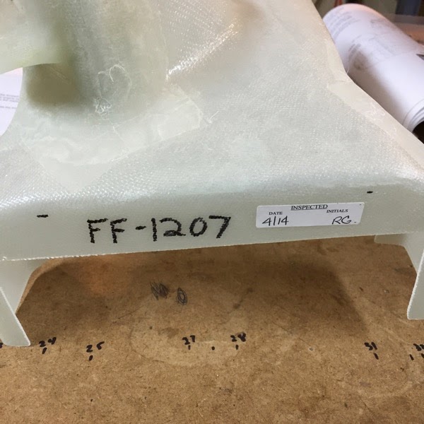
Cooling Shroud with marks

The cooling shroud gets fitted onto the engine in the next page.  The little marks that you see are supposed to line up with the top of the cooling fins when all is properly fit. 

46-03 Engine Prep, con't


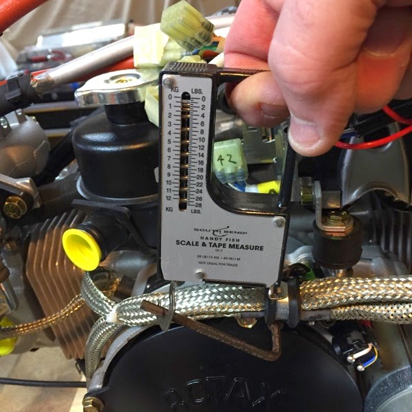
I ended up buying a bunch of tools today.  Below is a picture of a make-shift torque wrench.  I have a large collection of misc allen wrenches which I’ve been using on the Rotax.  Step 1 of this page states to torque the bolt to 55 in-lbs, but I only had the allen wrenches, not yet having purchased my new shiny (expensive) metric hex socket set.  I used the same fish scale from the front wheel, measured out 2.5” on the allen wrench and pulled until I got about 22 lbs on the scale.  Later, I checked again with my new tools and found that I came up to about 60 in-lbs torque.  not too bad for a Macgyver...


IMG 3984

make shift torque wrench

IMG 3985

Generator / Flywheel Assy


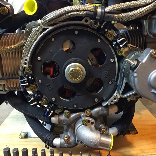
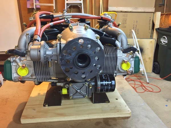
It wasn’t hard to remove the plastic cover, but it was surprisingly hard to move the flywheel to the proper positions to use feeler gauges to verify the gaps on the magnetic pickup coils (the 5 black ‘buttons’ with the blue & white wires).  The flywheel moves 2.43:1 relative to the prop flange.  The prop flange gets rotated with a couple of generic bolts leveraged with a large screwdriver. Despite removing spark plugs from the cylinders, there’s a lot of torque needed to rotate the engine.  I was very surprised, as I recall being surprised the other way with how easy my Lyc IO-360 rotated when there were no plugs installed.  I’m hypothesizing that the difficulty in turning the Rotax is due to the built in generator (as seen in the picture) that will always resist rotation to some degree.
 

IMG 3988

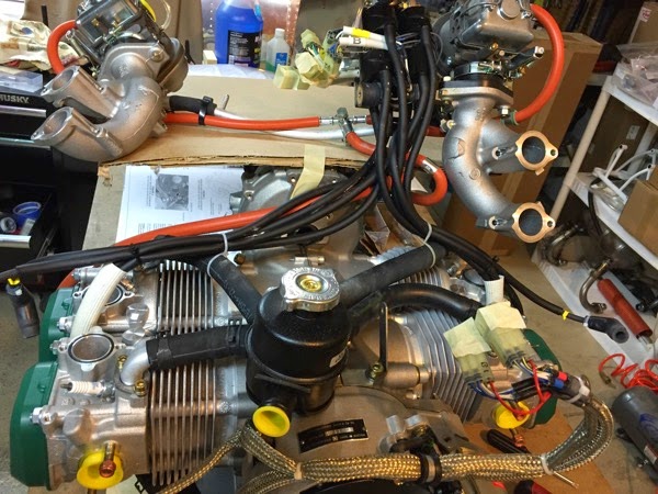
 Intake & Ignition removed from engine

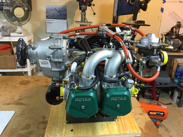
This feels like surgery.  I’ve disconnected the ignition system and then unbolted the intake manifolds, then flipped them up and over on their back, laying on top of the prop drive unit.  You can see the open ports into the cylinders (before I taped them up.)  Next step is to move the black 4-legged octopus on top.  That will give me a wide open view of the top of the engine so I can start fitting the cooling shroud. 
Monday, January 26, 2015

46-02 engine prep

The first page of this chapter says to take pictures.  lots of pictures.  then take more pictures as you take stuff off the engine. OK.  Here are lots of pictures.


IMG 3963

IMG 3964

IMG 3965

IMG 3966

IMG 3968

IMG 3969

IMG 3970

IMG 3971

IMG 3972

IMG 3974


IMG 3981

IMG 3981


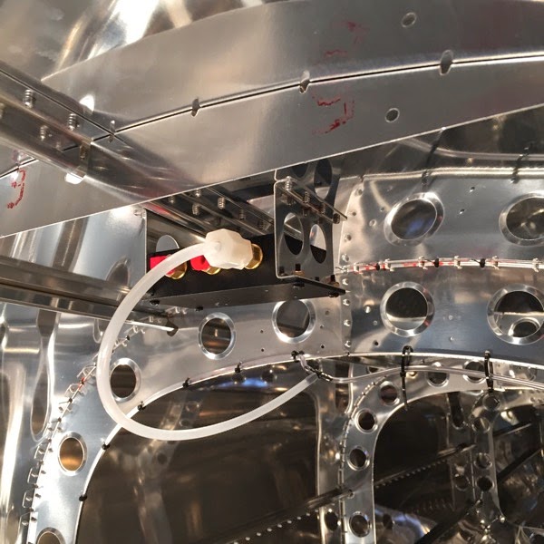
42C-16 #1 ADAHRS

This shows the installation of the ADAHRS  (Air Data and Heading Reference System) box in the tail cone.  I believe this location is selected to keep the device far away from the steel and electricity (magnetic fields) in the avionics and engine area.  The other steps on this page are the connections of the pitot system and wiring from the front of the plane, so they are deferred until after the mating of those halves.  On the other hand, the box is in its place, so it needed to be documented.  There is one pneumatic tube that you see connected: the static system is confined to the tail cone, so that went together already.
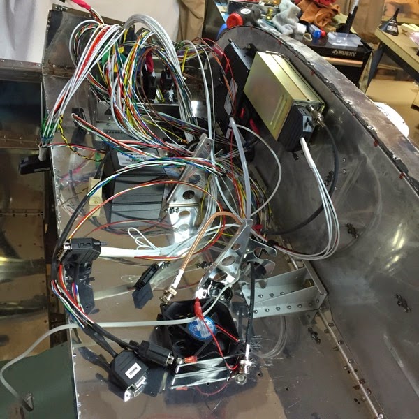
IMG 3960

ADAHRS

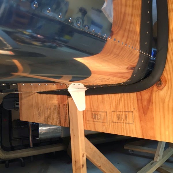
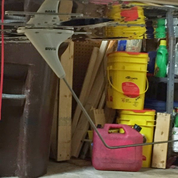
53-09 ADS-B antenna

Remember that doubler I deburred way back on 53-03?  I finally used it.  It goes inside the tailcone and is on the other side of this blade antenna.  It wasn’t until after I had drilled the holes that I noted that the doubler is actually oriented (e.g., it’s not the same pattern from fore-to-aft).  As luck would have it, I had inadvertently installed it the correct way.  whew!

IMG 3961

ADS-B antenna

42M-06 Antennae

Not much muss or fuss.  It was a bit of a wrist bender to get my fingers/hand inside the access holes and back down to put on the screws, but I’m getting used to such challenges. 

IMG 3956

Comm Antenna


IMG 3957

Transponder Antenna

44A-04 Pitch (forward) A/P Servo Install

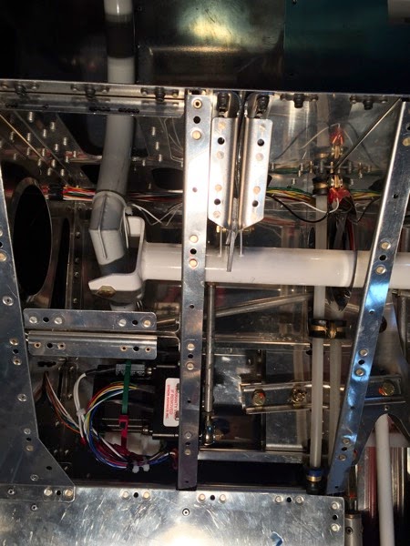
This servo is harder to see in the visual clutter.  As in the rear (roll) servo, it’s a black box.  In this picture, it’s in the bottom/left portion of the screen. Moving from mid bottom to middle of the image is a dull grey rod just parallel to the rib with some nut plates:  that’s the pushrod.  It’s connected to the bottom of the control column.  To tell the truth, I’ve been worried about this page for a while, but I was pleasantly surprised to discover it wasn’t that hard to install.


IMG 3950

44A-03 Roll (rear) A/P Servo install

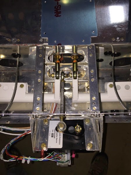
The servo is the black box at the bottom of the picture.  You can see the pushrod is attached to the main roll pushrod coming from the cockpit.

IMG 3948

44A-02 A/P pushrod fabrication

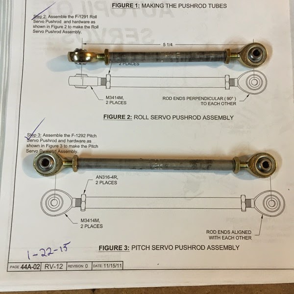
The autopilot uses two stepper/servo units.  One is placed beneath the pilot’s seat and uses a pushrod to move the Control Column forward & aft for pitch control.  The other goes back by the ends of the main roll pushrods and is actually only pushing on the Left flaperon assembly for roll control.  This page documents the creation of those pushrods. The remaining steps on this page are not applicable since the A/P is being installed on initial build instead of being retrofit.  

IMG 3944

Autopilot Pushrods

42F-04 ELT Installation

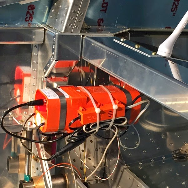
The wiring bundle is a bit of a kludge.  There are lots of cables for putting the ELT in one part of the plane and the antenna somewhere else.  in the RV-12, they are right next to each other so there are multiple cables that just get tie wrapped into a bundle and left in place.  As I look at this picture, I’m wondering how the R seat back is going to fit back in place.  Hmmm.... I’ll get back to you on this page if that’s a problem.

IMG 3941

ELT with audio alert module

42F-03 ELT bracket mount

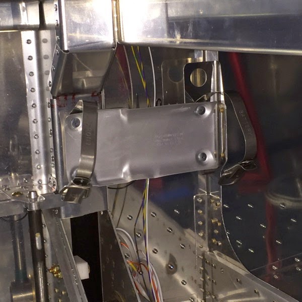
The ELT is a fairly straight forward installation.  The bracket that is at the rear needs to be installed before the fuel tank goes in, but the bracket isn’t delivered until you buy the avionics package.  There are two holes in that bracket (not visible in the photo) and no clear instruction as to which one is needed.  you can guess which ones I used first.  I ended up installing this about 1 cm too far aft, and needed to drill out the unusual rivets you see in the bracket.  Luckily, I had the spares on hand.


IMG 3939

ELT bracket 

Monday, January 19, 2015

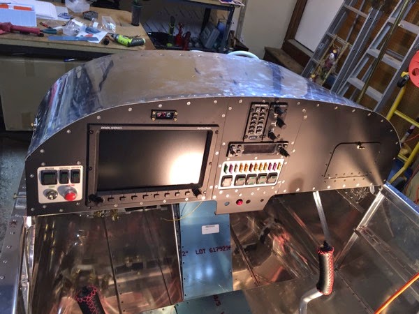
cockpit avionics complete

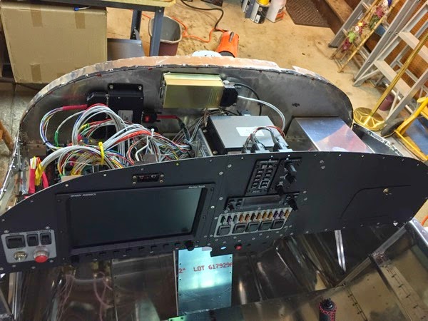
This isn’t a page out of the The Book, but I wanted to mark a milestone.  I’ve got all of the avionics boxes installed in the cockpit and re-installed the upper fuselage skin, so it looks more like an airplane again.  Some of the screws were a bit difficult to get threaded because things didn’t exactly line up at first.  I actually had one screw that snapped halfway through the nut plate.  I tried to drill it out and use a reverse screw remover but the drill didn’t want to touch the screw itself.  I just drilled out the nut plate and replaced it, then went from there.


IMG 3935

Front Panel


IMG 3936

last view of the rat’s nest


IMG 3938

all closed up!

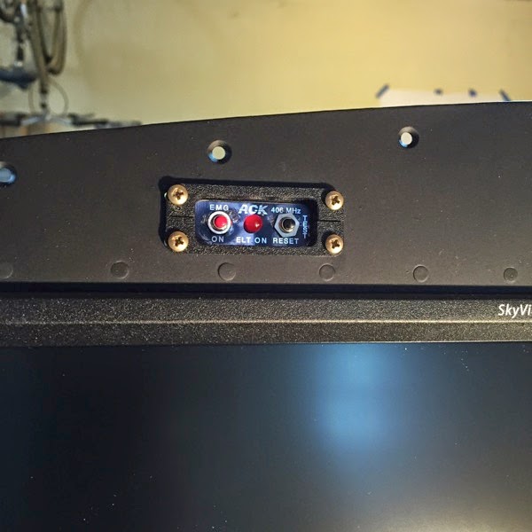
42F-02 ELT remote installation

This thing takes a really weird battery that took a trip to the Electronics store to find.  (I got another unusual batter for another ELT box while I was there.)  The front decal / screen got scratched up a bit when I put it back together.  <sigh>


IMG 3933

ELT Remote

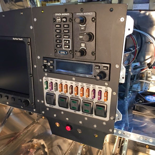
58-06 A/P Knob installation

This was a really easy page. Not!

Very straight forward on paper—just slide the boxes into the holes and connect up the cables.  But you know the reality, eh? 

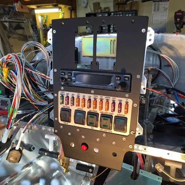
The nut plates I installed are not exactly right, perhaps just a mm or half a mm off, but that’s enough to make it almost install the screws.  The screws are very small, shiny allen head 6-32’s.  The allen head is the weak spot and will strip if there’s too much torque applied.  Three of the screws went in easily, two more required much creative cussing and fussing and removing and replacing.  (Luckily, Dynon sent me about 20 extras when I wrote and requested a few for the main display.  Thank God for good luck every now and then.)

I finally had to take the 6-32 tap and completely re-tap the nut plates.  I know that reduces their ability to hold, but I really couldn’t think of anything else.  If any screw backs out and needs to be tightened up, I’ll add some blue Lock-Tite.


IMG 3931

completed Center Panel

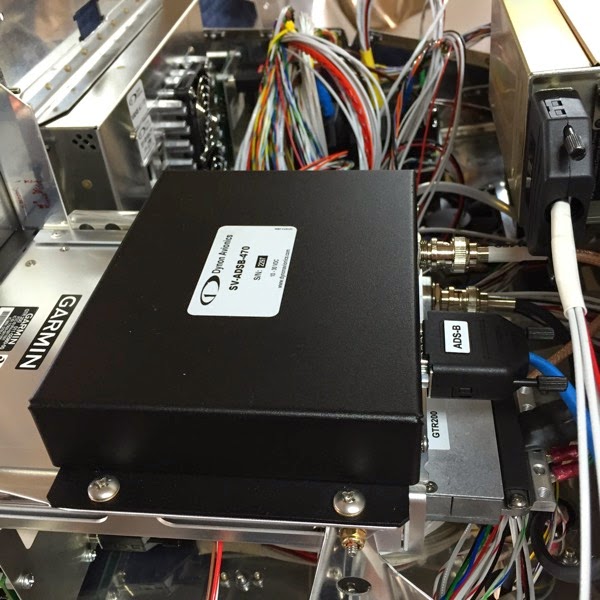
53-06 ADS-B install

The ADS-B box lives on top of the Garmin Comm with a couple of braces.  Oddly, the screws are a bit short for my taste, but I think they’re tight and will hold.  The cable didn’t fit inside the snap bushings and cushion clamps, so I secured it to other cables with tie wraps.


IMG 3926

ADS-B box

42C-06 Left Panel / Sky View install

Moving right along, we’re connecting the sky view next.

IMG 3924

 Sky View and left panel

IMG 3923

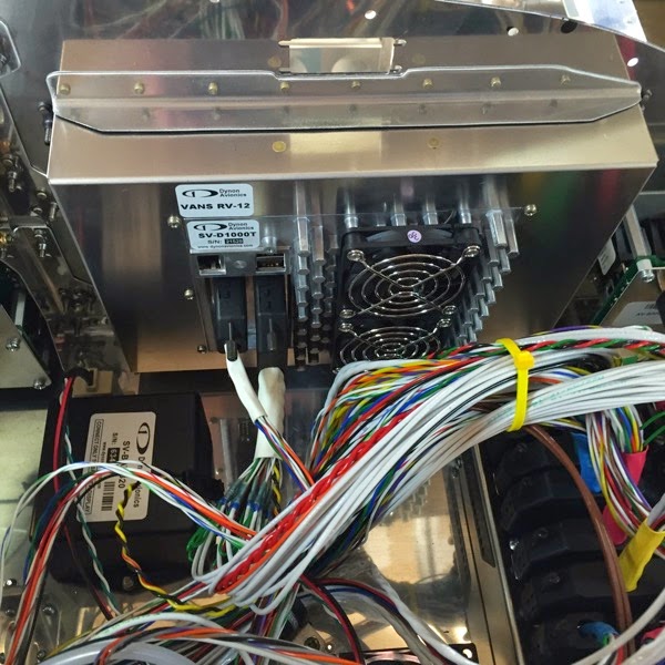
back of Sky View with cables


I didn’t like the way the wire bundles rubbed against the back of the SV computer, so I added the tie wrap to just tidy things up a bit more and get them away from the (hot) back of the computer.

Sunday, January 18, 2015

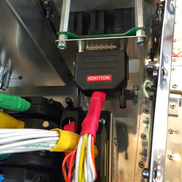
42M-08 Ignition Module wiring

This picture doesn’t look like much, but it is kind of impressive—“IGNITION”—all in red and everything.  What makes it memorable though, isn’t the harness, but the fact that the Left Panel is installed.

IMG 3921

Ignition Module Wiring Harness

42M-05 Switch wiring harness

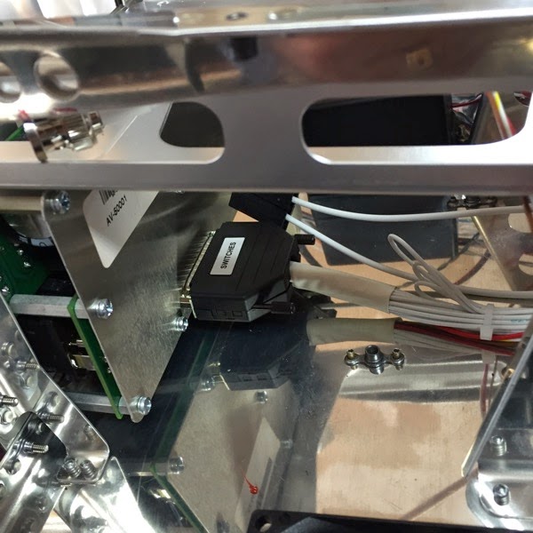
very trivial.  I even forgot to take a picture of placing the wiring harness between the A5000 and the Switch panel.  Turns out it came right back out to be modified for the Autopilot Knob package.

42G-03 Comm Radio/Intercom

It doesn’t look like much, but some work was involved in putting in the radio. You may recall that I spent a few hours filing the rectangular opening to ensure that the radio would fit through it properly, which I was able to accomplish.  On the bench.  After I attached the radio supports and mounts, I discovered that the radio sits on a shelf that lifts it about 2 mm relative to the front panel.  This meant that I had to takeout the recently installed switch module and remove the center panel and spend another hour with a dremel tool and flat file to open up the hole another 2 mm.  <sigh>

IMG 3918

42M-05 Switch Harness

OK, not much here, just the installation of the harness to the switch module.

IMG 3916

Switch Module Wiring Harness

42G-02 Center Panel

OK, now we’re beginning to put some order into the chaos.  Here’s the first pass at putting the center panel into the avionics bay.  The switch model is attached and the panel is screwed into the two uprights.

IMG 3914

Center Panel installation

44A-05 A/P disconnect switch

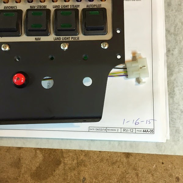
remember page 42C-03 that was rendered obsolete?  This is the other half of the connector that is on that page.  I had to re-paint this panel which is why it’s out of sequence (as if anything was in a sequence in the avionics.)  This connector will go to the new & improved A/P harness in a bit.

IMG 3913

Autopilot disconnect switch

58-05 A/P Knob wiring harness

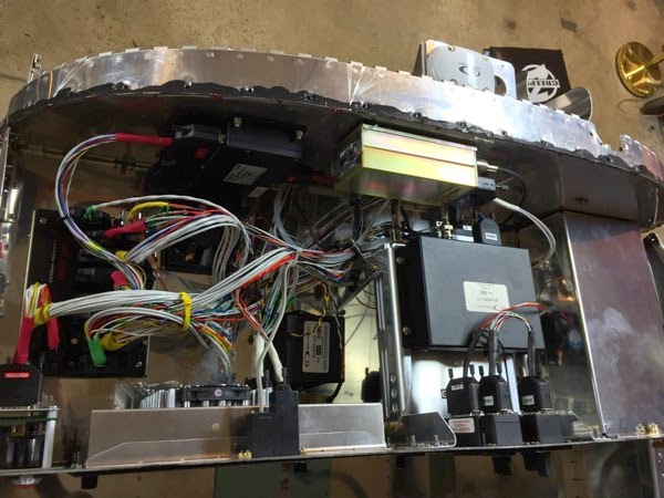
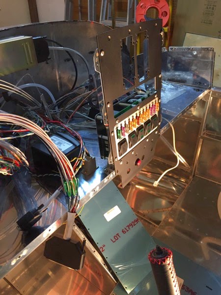
This picture theoretically  shows the installed harness for the A/P knobs.  Without a careful map, I think you’ll agree with me that it looks like a rat’s nest.  There’s only one more wiring harness that gets added to this mix, so this picture is probably your best bet for a view of maximum chaos.

You’ll also notice that the upper fuselage skin has been removed, despite my previous optimism that I could avoid this.  I suddenly realized that there was simply no way I was going to be able to install all of the brackets & hardware into that space, even if I could get the harnesses back there.  (BTW, in retrospect, I don’t believe I could have done that, either.)  Taking off the upper skin was the pain that I expected.  The bead of black gasket compound was extremely tenacious and challenging to disengage.  I’m pleasantly amazed that I didn’t crease the upper skin while taking it off. 

IMG 3911

rat’s nest

48-04 modifications to Switch harness

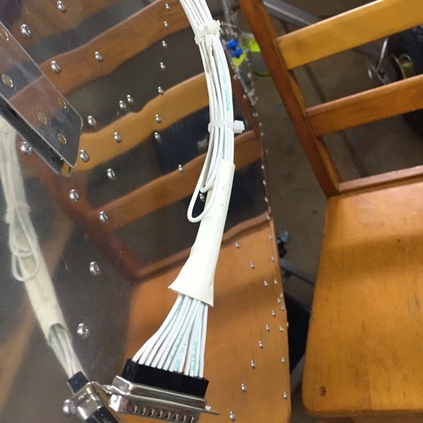
The retrofit kit for the autopilot knob panels require a bit of surgery  on the wiring harness.  Here, you have picture of 3 wires that were removed from the connector and folded back out of the way.  I briefly thought about removing the entire harness and tracing back the 3 wires to remove them from the far end.  The thought didn’t get very far.


IMG 3909

partially modified wiring harness

42C-03 Autopilot Disconect (obsolete)

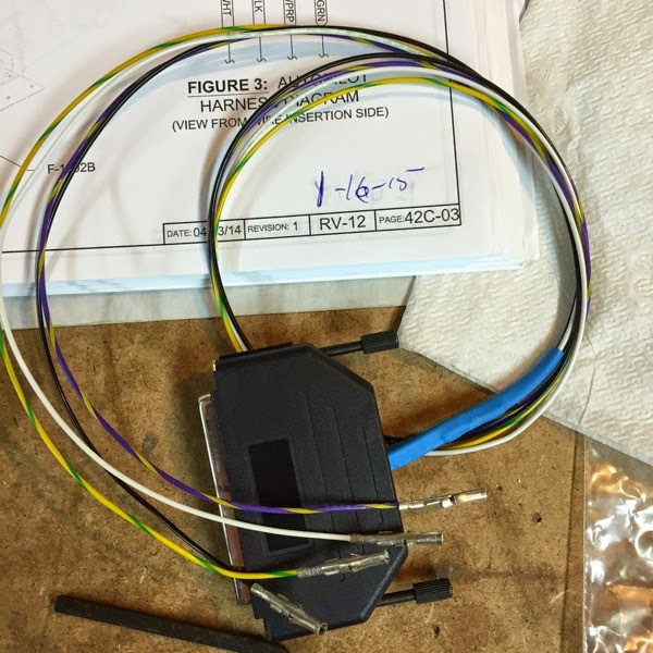
This is a page that I was waiting to continue.  It called for installing the cable pictured below and terminating the ends with a Molex receptacle, which I was not able to locate at the time.  When I got to the pages regarding the new autopilot knob kit, I was told to remove this cable and salvage the connector.  In other words, this page is essentially obsoleted by the knob kit upgrade.

IMG 3908

obsolete A/P disconnect switch wiring harness

46-23 nut plates for regulator (new position)

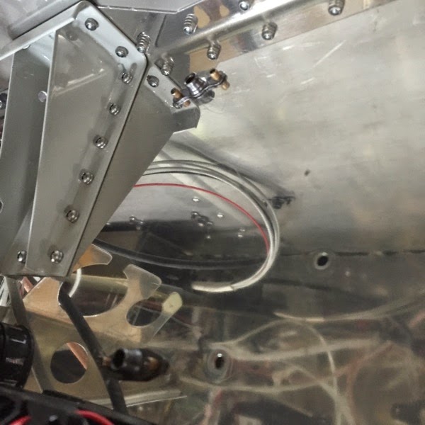
I’m installing the regulator inside the cabin, under the avionics shelf, rather than in the original position of inside the engine compartment.  The plans call for drilling holes in the bottom of the avionics shelf, and that’s a pain.  The view below shows the two nut plates on the upper surface of the avionics shelf.  (One is kind of fuzzy at the bottom of the picture, the other is fairly well framed.)  The Book also calls out that the shop heads of the rivets to the engine mount have to be on the bottom.  Luckily, I had already installed them in that orientation, so I didn’t have to drill out & replace those rivets.

 The Book gave a handout to use as a template, but getting under the shelf and taping it into position and drilling up (with the shavings getting around my safety glasses and into my eyes) was not my cup of tea.  I’m also not entirely sure that the scale of the PDF file is correct, as it doesn’t match the size of the regulator when I put it on the PDF.  Instead of that route,  I placed the regulator on the top of the shelf to get a feel for where it was going to go (under the shelf) and drilled one hole, then put a bolt through the regulator & the hole and drilled the other.  It didn’t turn out ‘straight’ but I’m pretty comfortable that the spacing is correct.  I need to get some (more) thermal conductivity paste before I mount the regulator itself.


IMG 3906

Regulator mounting nutplates.

45A-08 Relay Wiring

The boots are deceptively attractive, until you try to put them on short, stiff wires that don’t line up with the opening.  Ugh.

This page has one of those typical two-steps-forward-one-step-back kind of moment.  One of these wires needed me to do the final crimp of the ring terminal.  I managed to not realize when I dropped it from my tool and spent 30 min unsuccesfully scouring the garage to find it.  I gave up, went to Roush Hardware and got an off-the-shelf equivalent and installed it.  Next day, I found the missing part.


IMG 3904

Relay Wires

45A-07 wiring bundle ?

Same crappy picture.  I believe that the point of the page was to dress the wiring harness and get it through the cushion clamp attached to the engine mount.

IMG 3901

same crappy picture of the wires though the (hidden) cushion clamp

45A-06 Manifold Pressure Sensor

If you look very carefully at the very top of the picture, you will see an orange structure with 3 wires.  That’s the subject of the picture.  (I believe you will join me in my hope that I am a better pilot & builder than photographer.)

IMG 3901

crappy picture of Manifold Pressure Sensor

45A-05 Fuel Pressure Sensor

I got a lot done over the last few days.  As usual, I typically only make these posts when I have down time at work (and I can’t be at home and build).  This was mostly avionics, and those pages went by quickly.  I’ll probably have a few pages with just a picture and a page number, but no text because there really isn’t much to describe (or remember well enough to describe.) 

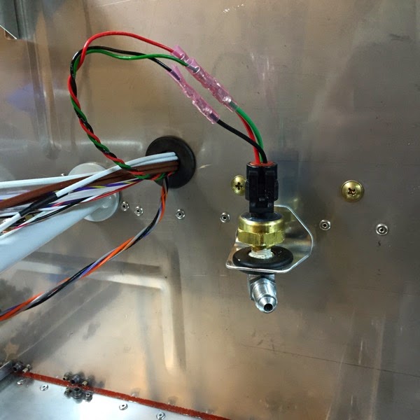
 I was just ready to hit the Post button for this page when the picture caught my eye.  The sensor is held in place by friction from the modified grommet.  I think the weight of the fuel hose will pull that down such that the narrower (threaded) portion of the nipple won’t be held firmly by the grommet.  I’ll double check the book, but it may make sense to invert the assembly so that the weight of the hose holds it in place rather than pulls it loose.

IMG 3899

Fuel Pressure Sensor

Sunday, January 11, 2015

45A-04 Firewall Forward Harness

Despite the 1st instruction stating to remove the Top Skin assembly (to open up the avionics bay) I think I’ve gotten through the toughest part of the installation without having to do so.  I was able to snake the Firewall Forward Harness through the firewall penetration by taking all of the wires (except for the yellow wire to the regulator) and laying them into a length of painter’s tape and rolling up the tape to make a “smooth” shape to thread through the avionics bay wiring nest and out the firewall penetration.  I learned from previous attempts at this trick.  There are 3 connectors with bulky shapes that all terminate at the same length.  I staggered them in the tape trough and let the slack wire be at the proximal end, then later tightened them up.  

The power wiring harness has a very bulky (heavy gauge) wire that is actually bifurcated on its way to the regulator, and that needed to go through the inferior snap bushing below the avionics shelf (new location of regulator.) That was a pain to pass through the tightly packed snap bushing and I needed to remove the pitot line, pass the power regulator wires, and re-insert the pitot line.  

The instructions also imply that the pitot line (Aft Pitot Line to Pitot Line) gets spliced within the avionics bay, but mine was able to be spiced forward of the firewall.  I may have a shortage at the aft end (AHARS), but if so, I’ll just add a splice back there.  It wasn’t tough to slide the lines into the splicing tube, so I added two tie wraps for additional security.


IMG 3897

Firewall Forward Harness

Saturday, January 10, 2015

45A-03 battery wiring

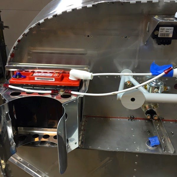
Just the large gauge wires from the battery.  Note that the (-) terminal is open, as we don’t want any unexpected power flowing through the system!  I also had to remove the fuel ‘short circuit’ I built for fuel testing.  There’s a bit of blue tape over the open fuel lines to prevent any debris from entering.


IMG 3895

Battery wires

45A-02 Battery, Relays

Not much fuss.  Build up a support bracket to hold down the battery and install the main relay and starter relay on the firewall. 

IMG 3893

installed Battery, Relays