Monday, November 25, 2013

16-03, Stall Warning Installation

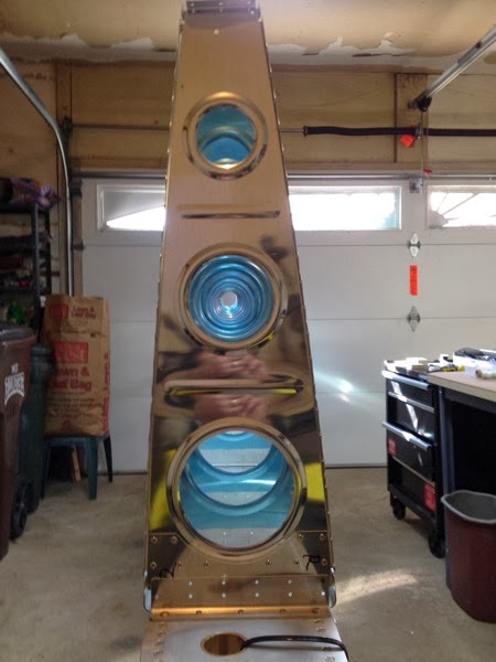
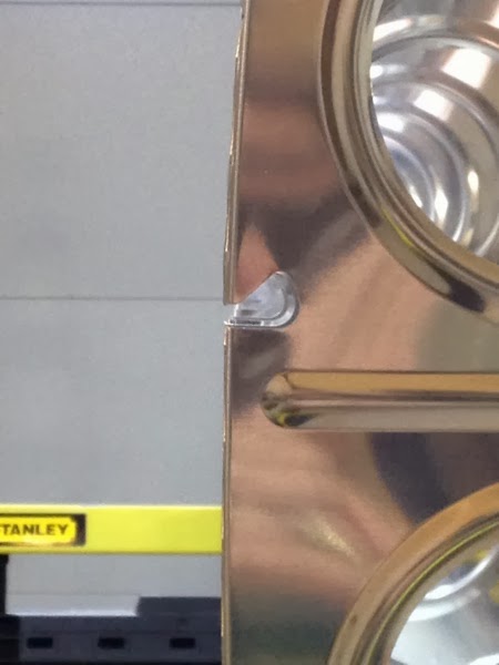
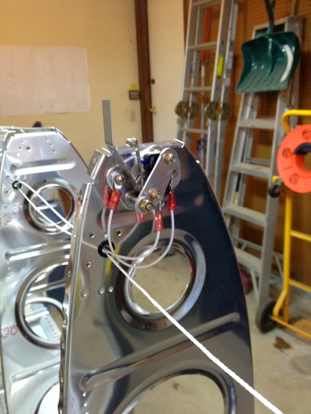
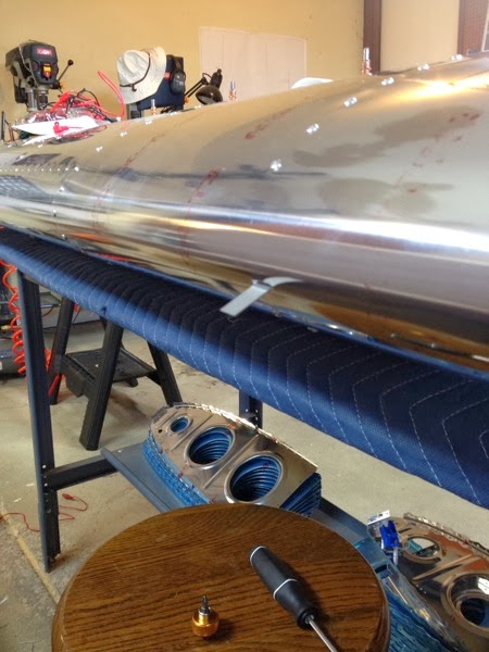
This was, as expected, tricky and tedious, but not nearly as tricky as I think it could have been!   It does’t look like much, does it...?
IMG 0143 2

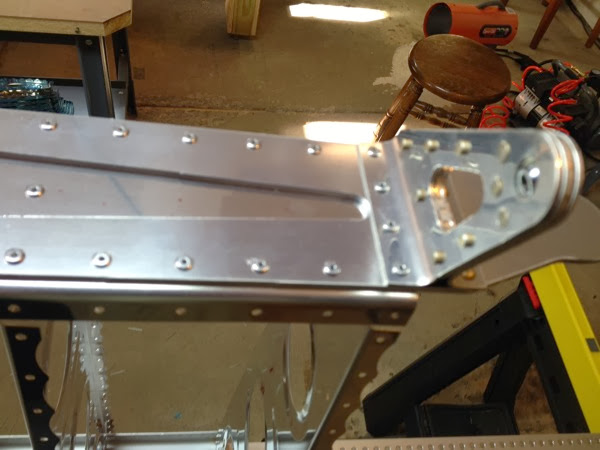
Well, that little tongue sticking out is the stall warning switch.  When the plane is flying at a very high angle of attack, the relative wind will force that switch up instead of down.  That closes a microswitch hidden beneath the leading edge, thus notifying the pilot of an impending stall.  Can you see how much that switch can move?  Not much!  In other words, I had to get the alignment of the switch assembly to be juuuuust right.

I have rearranged several of the construction steps for just this event.  In order to align the switch, I reason that the lower mid skin needs to be in final position—cleco’ed just isn’t good enough (more about that below) for this precision of alignment.  Accordingly, I only rough positioned the stall switch assembly last week and waited until I had riveted the lower skins on their lower side and the leading edge.  In other words, the skin was in final position.

I was able to reach in the access hole and move the assembly with little difficulty.  Much to my surprise, it took less than a minute to get the assembly rotated such that the stall warning vane was (1) 90° to the local curvature, and (2) audibly activated the microswitch.  I jury rigged an old analog volt-ohm-meter to the contact in the connector (this would have been nice to have thought about prior to getting all fancy and installing the connector) and verified that I could trigger the VOM with the stall warning vane.  The next hour did not go so well.

There was just no way to see the screws in order to tighten the assembly in place.  I tried a mirror; my hand blocked my own view.  I tried the solid state borescope; way too many reflections, and an oddly long focal length.  I tried mating Lada’s and my iPhones with a FaceTime (video call) connection and using one iPhone inside the wing; guess what?  Aluminum does a great job of shielding the wifi connection.  Resorting to braille and luck, I was able to get the screwdriver engaged in the appropriate screw.  The first n times, rotating the screw also rotated the assembly, thus mis-rigging the vane.  I finally got the thing tightened and—miracle of miracles—it was still in good position.

Why am I so happy that it only took an hour to tighten two screws?  Because the instructions intimated that it was “OK” to bend the arm of the microswitch itself if there wasn’t good switch action when the vane was 90° to the skin.  I really don’t know how I would have tried to accomplish that!

As mentioned above, “cleco close” isn’t good enough for some situations.  I riveted the leading edges of the skins prior to doing the above stall switch adjustment.  I recalled reading that an awl was good for recalcitrant holes that wouldn’t accept a rivet.  I had disregarded that, as I had perfect alignment with clecos.  Well, I purchased an awl and discovered that it works like a jiffy!  A touch of elbow grease provides (1) exact alignment of holes and/or (2) enlargement of the holes such that a LP4-3 is a tight fit, but not a fight to fit.  I had to #30 drill exactly 1 hole because an underlying structure did not permit the awl to go the required depth.  It’s now sitting in the honored space reserved for ‘daily use’ tools—my practice toolbox.   
16-04, wing electrical connectors

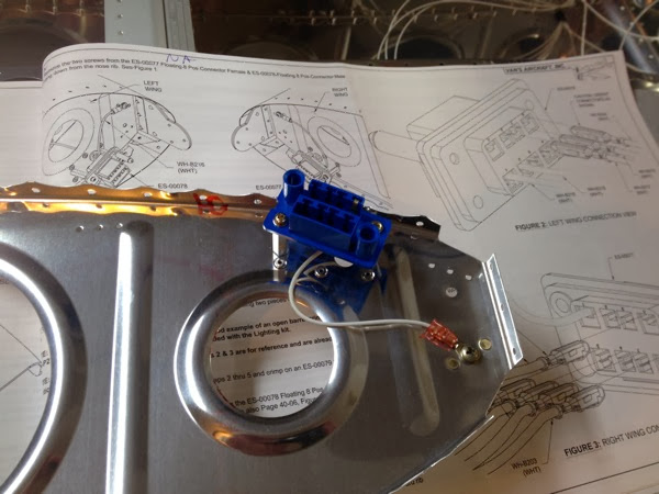
No big surprises here, the wires have already been pulled and it was pretty straightforward to assemble the electrical connectors.  I had a bit of trouble with crimping the pins on the insulation, but the crimps are strong and serviceable, if not pretty and elegant.  Oddly, the smaller crimps on the conductors are very nice and look good (with suitable magnification.)

Van’s used an interesting approach for the connectors.  One wing gets the male, the other gets female.  Logically, I am expecting that there will be a corresponding female and male connector on the fuselage.  To pass the time and entertain myself, I spent a few bucks to get an additional set (expecting it next week.)  I’ll dummy up the fuselage portion of the wiring and connect a suitable 12v supply and beeper circuit.  When the wings are complete, and the lighting kit installed, I will be able to test the lights (position, strobes, landing) and stall warning with the wings in their cradle.


Right wing electrical connector, with ground wire attached.  The connector is only loosely screwed to the standoffs, as I will need to install all of the remaining wires for the strobe, position and landing lights.

IMG 0138 2


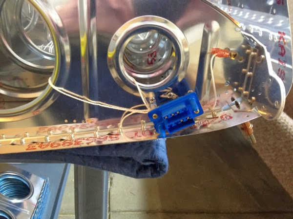
Left wing electrical connector, in situ. The ground is visible, but the strobe & position lighting wiring isn’t seen behind the connector itself.  There is a string tied through the lightening holes, as called out by the instructions.  (I don’t know why we would leave another string there, unless its just an accepted practice for (inevitable) future mods.)  You can see the leading edge of the wing is not attached and nearly vertical at the extreme right edge of the picture.

IMG 0140 2

Thursday, November 21, 2013

Decisions, decisions, decisions...

I’m at a point where I need to decide if I’m going to go EAB or E-LSA.  For those who may not be familiar with the acronyms, those represent Experimental Amateur Built and Experimental-Light Sport Aircraft, respectively.  Long story, short:  EAB is the traditional Experimental category and I can follow the plans as closely or loosely as I see fit. (In other words, I can make modifications.)  I would be the Builder and I could do my own annual inspections, or an A&P could do so.  I can never rent the aircraft or otherwise receive any compensation for flight time (that includes cost sharing), although I could be paid as an individual since I hold a commercial license. 

If I stick to the plans (to the letter) then the plane will be an E-LSA and is essentially a “factory” plane of Van’s which I happened to assemble.  I’m still not completely sure of the rules re: who can do annual maintenance, etc., but I know that you aren’t restricted to just hiring an A&P.  

The EAB must be prominently labeled “Experimental”, not so for the E-LSA.  Might scare potential passengers.

It’s been discussed on VAF that it will be easier to sell as an ELSA vs. EAB, but there’s absolutely no data to support the claim.  (to be fair, there’s no data on resell values of either certification of RV-12’s to date, so there’s no data to the contrary, either.)

Those are the facts, but they don’t address the emotion.  I’m currently leaning toward EAB as a matter of personal pride, and a desire to implement a couple of mods. The mods aren’t big, but big enough to make a legal distinction.  I’d like to put in angle-of-attack and a 2nd landing light.  I’m not sure about the split bulkhead, but it sounds like a good idea so far.  There’s also an issue with the dorsal skin being too flexible in the vicinity of the AHARS computer and it may need a stiffener of some sort.  These are the things that make the EAA a fun place to play, and being registered EAB would be part of that tradition.

More to follow, but I think I’m going to go EAB unless I learn something else in the next week or so.

Monday, November 18, 2013

17-02 (L), Left Lower Wing Skins

Not too much to comment on, the lower skins went on without any issues.  :0)

This is slightly blurry, but you can see the inboard skin hung on the ribs.  The spar is suspended on sawhorses and the skin is hanging on the nose ribs.  On the R side of the image you can see the string and stall warning switch wire.  

IMG 0133 2

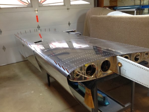
 Here’s the finished product (finished with respect to the page, anyway) resting on its upper surface.  

IMG 2775

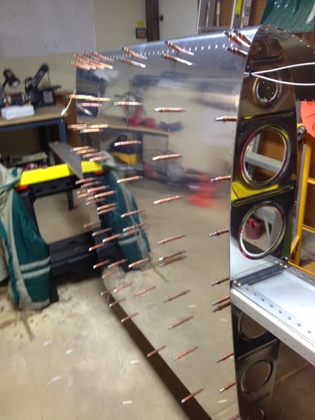
Next steps (which are out of order) is to attach the electrical quick-connect to the inboard rib (will do R wing inboard wing at the same time) while the upper surface of the lower skin is still open.  Then I will rivet down the leading edges of the inboard and outboard sections.  Finally, the middle skin will be clecoed in place and the stall switch will finally be adjusted, then I’ll finish up by riveting the leading edge of the middle skin.  At that point, I will put the L wing on the cradle and start on the R wing!

(This assumes that I get any days to myself to work on this.  My work schedule is looking pretty ugly for the next few months...)

Saturday, November 16, 2013

15-04, main ribs L wing

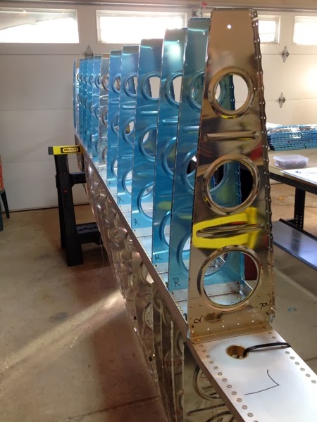
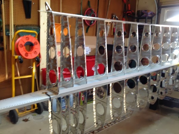
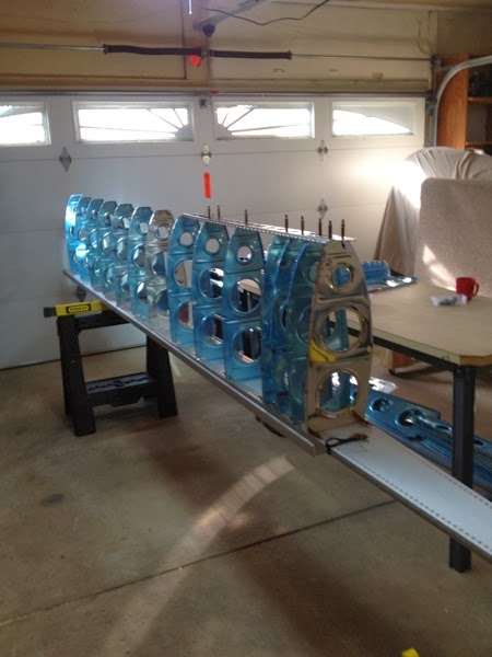
Nice view of the main ribs clecoed in place.  I’ve been pretty worried about my ability to make sure that I get all of the proper “L” and “R” pieces.  Sure enough, there’s another error in this picture.  I’ll let you look at it a bit before you see the answer below.


IMG 0128 2


Sure is pretty, isn’t it?  I actually like the sky-blue (голубой) color of the protective plastic.  I might look for something in that shade for the final paint job.  If I’m really feeling whimsical, I’d even think about some decals that look like the manufacturing stamps on the plastic and put those on the plane.  Any Van’s builder would get the joke, but not anyone else... 

IMG 0129 2


Just another shot, looking at the completed skeleton. IMG 0131 2


Here’s the clue I alluded to earlier. See those nice LP4-4’s?  I have to drill them out to remove the R main rib with the doubler and install the correct (L) doubled rib as called out in step 6.  How did I miss that?  By not only installing the wrong rib, but installing it on the wrong side of the flange so that the double mirroring made it a very, very subtle thing.  As you can see, I had the rear spar fully attached and only discovered the error after clecoing the main skin and noting that the very final holes (this rib) didn’t line up... : (

What’s the good news?  I hadn’t riveted the skin! :0) 

IMG 0132 2

15-05, nose ribs L wing

I did this page out of sequence in order to build the wing on saw horses instead of the table.

Before:

IMG 2753


After:

The ribs are clecoed in place, prior to riveting. I try to double check everything before committing to rivets and it paid off.  The inboard rib is flat out upside down (equivalently:  flanges inboard instead of outboard) in this picture!  Quick reversal, and all was well...

IMG 2754


A nicer picture showing the lightening holes aligning well.

IMG 2755

This is even cooler—the nose rib cutouts that will accept the upper skins are also as well aligned as anything I can photograph.  It helps me feel more confident that I’m going in the right direction.

IMG 2757

16-02, Stall Warning Switch

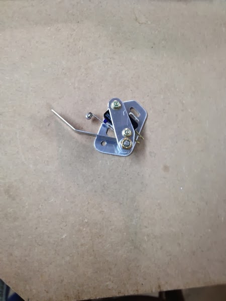
11/13/13:  Here’s another deviation from the strict order of The Book.  I’m building up the stall warning switch so I can install it on the appropriate rib before that rib gets riveted to the spar.

IMG 2758

 In turn, I’m not following the strict order of installing the ribs, either.  I’ve clecoed the nose ribs to the L spar to make sure that I’m putting the correct “L” and “R” ribs in place before committing anything to a rivet.  The stub spar has also been attached to the inboard nose ribs, although not without a comically bad attempt at installing a rib upside down (see page 15-05 for that story.)

By installing the nose ribs first, I can turn the spar over on the sawhorses and avoid putting any side loads on the ribs at all.  I’m very cautious about them, as they are quite flimsy until properly skinned.   While the spar is forward=up, I want to get the stall switch installed, the nose ribs attached and then do the test fit of the lower skin with respect to the stall switch.  I’m hoping that keeping the wing oriented this way will relieve most of the clumsy maneuvering that I anticipate in fitting that skin over the switch.   Once I verify that that the stall switch is in a good position, I’ll flip over the wing and do the main ribs, then the main (lower skins).  With the lower skins in place, the wing will be mechanically much more stable.  Then it goes into the cradle, and I repeat the process with the R wing.

After the main skins are on, but before the upper skins close out the wings, I’ll do the wiring kit.  By that time, it should be Dec 9, at which point I will meet Bob Leffler who is an EAA Tech Counselor.  He’s going to come over to my shop and check out my work.  Although not really required, I want to leave the wings open for him to be able to look around.

I’m still not sure if I want to go EAB or ELSA.  There’s a matter of increased pride in both directions:  by going EAB I can take on the pride of “American independence” and it will be my name on the data plate.  By staying ELSA, there’s the pride of “yes, I can follow directions” and have potentially easier time selling it.  (Do I really care about that?  Not sure....)


11/16/2013

It’s been a busy weekend, and I’m posting several pages, so feel free to get confused as you read through this.  Here’s the stall warning switch installed on the rib, prior to being skinned.   Note anything?  Take a look at the orientation of the stall warning vane.  It’s angled up, not down.  Needless to say, I did note and correct that little ‘oops’.  Luckily (or is it skill [no]) I did note this before attempting to put the skin on and thus damage it.  While I was removing / replacing the stall switch assy, I noted that it was very rough to pivot, and would thus be difficult to adjust when the skin was on.  I sanded out the inside of the race that the upper screw uses to permit pivoting and it’s better, although still not smooth.

IMG 0127 2

At the time of this posting, I have attached (riveted) the outer and inner lower skins, and clecloed the middle skin in place over the stall switch.  It’s not yet adjusted for proper operation.  I’m planning on riveting down the leading edges of the inner and outer skins so they aren’t flapping around and while the wing is right side up, adjusting the switch.   With the access panel on the bottom and the open leading edge on the top, I hope to be able to do this adjustment without needing to remove the skin at all.  

Monday, November 11, 2013

Wing Caddy

Side project!   I’ve been putting together ideas for a few weeks and finally got around to buying the lumber and just building the wing cradle.  It’s getting to be a bit tight around the garage, but I have a place to put the wings.

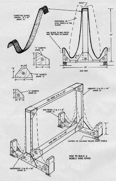
I started off with the “generic wing caddy” from the EAA site:

EAA generic wing caddy

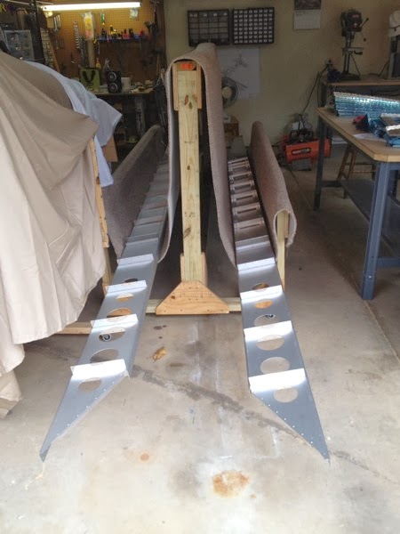
A few modifications; the outrigger uprights are 24” instead of 12”; the main piece is 8’ long, and I used a full piece of carpet instead of just two straps.  I was amazed at how hard it was to cut all of that wood.  I also used lots more screws than I thought I would.  This thing is built like a tank, definitely overkill.

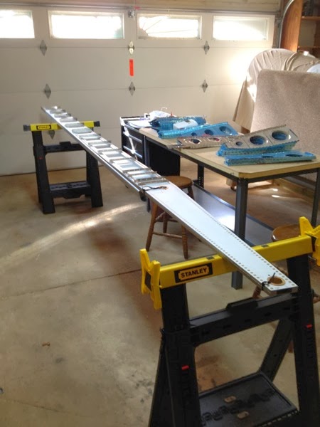
Here’s the photo with the wing spars resting down in the slings.  I’m letting their weight settle the carpet before I secure the top piece with some more staples.

IMG 0123 2


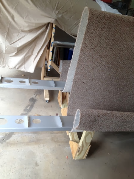
You can’t see them under the lip of carpet, but I did recycle some of the lumber from Van’s crate.  The other wood is cheap stuff from Home Depot—much wetter & heavier :(


IMG 0124 2

Thursday, November 7, 2013

15-03, Main Rib prep

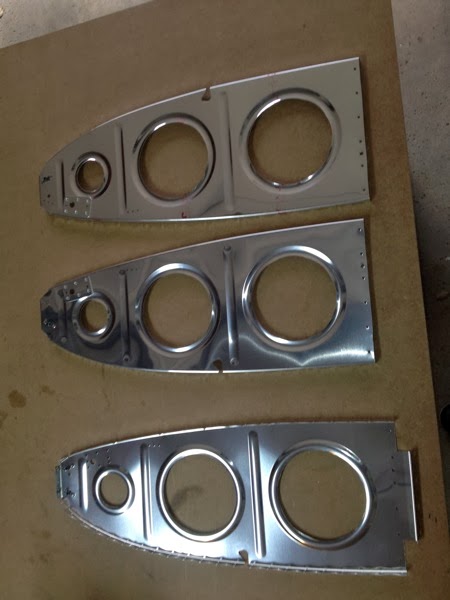
The majority of preparation for the main ribs was to flute flat and remove nearly all of the forward flanges.  This picture shows all of the main ribs and the hinge assemblies after they were deburred and re-clecoed.  

IMG 0116 2

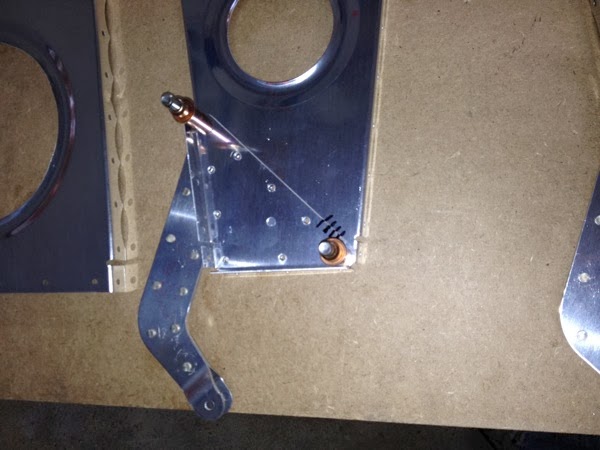
Example of a main rib clecoed to a hinge rib and flaperon hinge assembly.  Note the hash marks used to allow re-assembly of all match drilled sets.  The directions were very confusing here; the R and L designators of the Hinge Ribs seemed random.  I played with trying to put R hinge ribs on L main ribs (and vice versa) as called out, but they just didn’t fit together.  Putting R to R and L to L was much better fit and agreed with the diagram.  There have been a few other places where R and L nomenclature has been wrong, so I will be searching VAF to see if I’m not alone.

[Update 11/13/13:  I came back to trying to fit the hinge ribs and main ribs the way the book calls out.  The advice to let things settle in your mind and try again is excellent; I had actually mated the parts as called out by the book, but didn’t realize it.  My best guess is that I had the R and L hinge ribs incorrectly identified.   As it stands now, the R hinge ribs are attached to the L main ribs and the L hinge ribs are on the R main ribs.  Go fig! :0) ]

IMG 0117 2


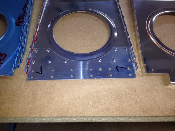
Doubler plate attached to L main rib.

IMG 0118 2

15-02, Nose Rib Prep

The first step in working with any ribs is to flute the flanges so that the rib lays flat.  It took me a long time to do this for the tail feathers, but I was amazed at how fast the process went this time.  Something ‘clicked’ in my hand/muscle/insight system and I was able to flute these ribs with just 4 - 6 gentle motions which all had a visible effect.  This photo shoes a fluted rib in the foreground and an untouched one in the background.  Note the background rib is visibly bowed up and you can see a sliver of light under the middle lightening hole.  The foreground rib is laying flat after only a few flutes.


IMG 2722


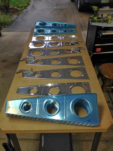
Here’s the entire collection; some with nose flanges removed, some with rear flanges removed, some with none removed, and others with intact nose flanges but removed rear flanges.  The removed nose flanges will (probably) be where the stub spars attach.  The varying lengths of the rear flanges are probably due to the stepped nature of the spars with the thickest parts of the spars being closer to midline of the aircraft.

IMG 2725


These have doubler plates and/or K1000-8 nut plates for the electrical connections and the stall warning vane, respectively. 

IMG 2730

Sunday, November 3, 2013

14-03 Rear Spars

This was a pretty straight forward sheet.  Rivet together the doubler plates, a curved flange and the hinge assemblies that had just been blessed as “acceptable" by tech support at Van’s.


IMG 2719