Showing posts with label Wings. Show all posts

Thursday, June 4, 2015

40-10 Nav/Stobe attach

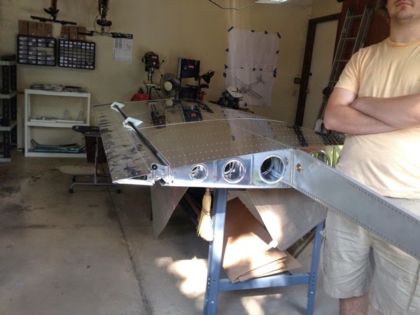
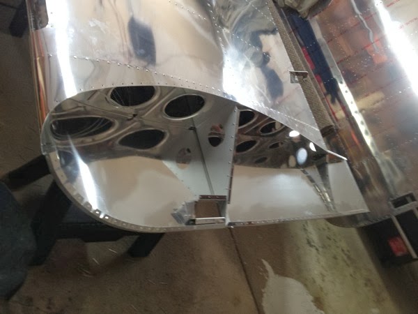
Here’s one that I was afraid of screwing up, and I did.  The Book calls for using fuel tank sealant (visible as the dark grey under the edge of the fiberglass).  I got everything all set and finally mixed up the goop and went to work.  After I had pulled about half of the rivets on the Left wing, I noted that I had neglected to pull the wing’s wiring harness through the opening of the fiberglass and it was now firmly buried inside the wingtip.  I said a few choice words (loudly, apparently, as Nikolai was able to hear me and showed up with concern for my well being).

I elected to keep working while the goop was still usable and proceeded to finish on the R then L (after pulling the cable through the fiberglass).  Many, many, many years ago my high school teacher told me a story wherein he did an electrical job in exchange for a “fish”, a stiff metal filament used to pull wires through walls.  I bought one when I had my first house in California (1988) and I wanted to pull ethernet wires. Never used it again until today when I pulled the connector close enough to get it with a pair of forceps and was able to deliver it through the opening.  Whew!


IMG 4341

Landing Light & Nav Light


40-09 wingtip wiring

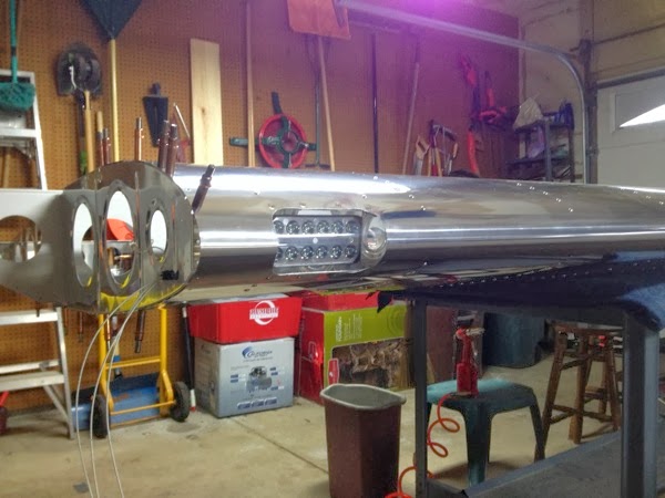
The wiring for the wingtip has been hanging out inside the wing for a year.  Now it was time to terminate it (and the wires on the Nav/Strobes, too.)   I noticed that one of the wires on the R wing was a bit longer than its partners, but I just cut it to length and went on.  Remember Van’s Dictum?  If something doesn’t look right, it’s not.

I did invest several hours cobbling together a test cable that had just 8 straight passthrough conductors for the wing connectors.  I used that to electrically connect each wing to the plane and verify that everything worked.  Well, it did on the Left but no strobe on the Right.   Basic trouble shooting eventually led me to the wing root connector being at fault because there was no wire in pin #8. I reached in the wing and found it about 10” outboard.  That’s when the extra 10” I trimmed suddenly made sense.  Damn.  About an hour of doing other things while my hind-brain chewed on the problem led me to the easiest solution of splicing the length back on the outboard end and pulling the wire medially again.  Luckily I had many spare pins available to re-terminate the wire and we were back in business.


IMG 4338

Nav/Strobe wiring harness

40-08 wingtip light prep

By the way, I forgot to mention last posting that it was very convenient working on the wings while they just sat in their cradle.  I had been mentally preparing to re-organize the garage and temporarily put the wings on a table.  When I looked at things, it turned out that they were ideally situated to work on.  Nice!    The same good luck held for the wing tip lighting project.

Now, this is a project that I’ve been dreading for over a year.  I was simply not able to face dealing with the fiberglass and epoxy stuff involved.  I had read the instructions multiple times, but it never made any sense to me.  Now, after doing the cowling, it’s much less confusing.  Onward!


IMG 4336

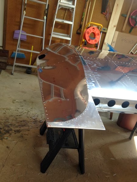
prepped fiberglass wing tips


The fiberglass was trimmed to the appropriate line, holes were drilled, access ports were opened, and wax generously applied to the wing tips.  Epoxy got mixed up and sloshed inside the fiberglass edges then the whole thing was clecoed to the wing tip.  I didn’t quite get a complete fill on one edge and will probably do a re-work by mixing up more epoxy/flox and injecting it into the gap, but it’s definitely usable in it’s current state.  (The rework will probably happen when I tackle the very last project—wet layup of the canopy fairing.)

SB 14-11-03 Wing Skin / Spar Flange rivet wear

This service bulletin came out last fall and calls for annual inspection of the rivets at the bottom wing skin and to add this doubler if any signs of wear.  I elected to just install the doubler and not wait.  Note that the SB still calls out annual inspection for wear, but this makes it extremely unlikely to find such.  There are no less than 4 separate rivet types in this doubler.  The zig-zag row on top and the lateral portion of the middle row are ordinary LP4-3’s.  The next 8 in the middle row are 5/32”, and the inner most rivet (still on the middle row) is a Cherry Max.  The bottom row of zig-zag are very low profile (inner surface) since there is very little clearance below them.  All in all, it was a nice day of good old fashioned metal work.


IMG 4330

wing root doubler

Thursday, July 24, 2014

30-all. fitting of Wings

 Big day!   Nick (“Big Nick”—fiancĂ©e to my daughter, Melena) helped with the lifting and moving to get the wings fitted onto the fuselage.  Looking through the instructions, I noted that I needed to fully deflect the ailerons upward to check for interference.  Oddly, the instructions have you insert the wings & remove them, then tell you to fit the ailerons.  That’s dumb.  We fit the ailerons first.  Biggest problem he had with that was getting two washers at a time on each side of the applicable bolt.  I have a very cool tool—washer pliers—that permit the placement of one washer, but doing two required some jiggling.  Overall, not bad and the ailerons went on nicely.


IMG 3473Left Aileron installed on wing 


IMG 3475

Right Aileron installed on wing 

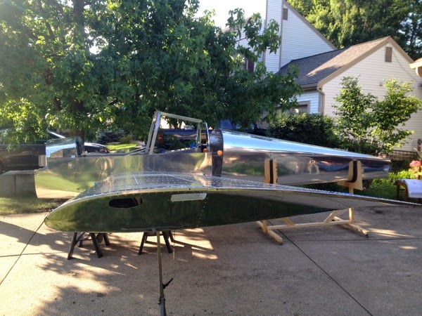
After that came the big event of the day.  We moved the fuselage out onto the drive way and shifted it from the cradle onto heavily padded sawhorses.  Nick held the wingtip and I directed and guided the spar into place.  It got hung up due to interference from the fuselage skin (lower) and the F-1204H Bulkhead Caps.  I used a dremel tool to shave off about 1/8” and we tried it again.  Viola!  The Left Wing was installed!  The Right Wing went in on the first try and we had something that actually looked like an airplane!  Just for fun, I pulled the tail cone out of the garage and positioned it behind the fuselage for the photos.


IMG 3477

Left Wing installed on fuselage 

IMG 3478

Both Wings installed!

IMG 3480

Left Wing

IMG 3481

Right Wing

IMG 3485

Wide angle shot

Thursday, February 27, 2014

18-06 RIGHT, completion of flaperon

This was a fun day.  Just worked and worked and worked and had a great time.  It felt very good to get a lot accomplished and have a finished product to show for it.

IMG 2954

Actuator of R aileron

IMG 2955

Close up of support bearing

IMG 2956

Finished Aileron.


Note the straps on the large crate.  I was kind of excited to get into that crate and take a look at the finish & fuselage kits.

18-04 RIGHT, bracket attachments

Time to do some catch-up documentation.  I’m writing this on 3/14, but have dated the postings to the days that I took the pictures (completed the indicated steps.)  As such, the textual description may be a tad sparse.


IMG 2950

Right Pivot Bracket

IMG 2951

Right Actuation Bracket

This looks like it’s crooked, but that’s just the sloping edge of the bracket.  

18-05 RIGHT, Internal ribs & counterweight

well, I didn’t take a picture of this one.  Sorry ‘bout that.

18-06 LEFT, completion of flaperon

No muss, no fuss.  Just some repetitive and satisfying riveting and assembly work.

IMG 0176 2Left Flaperon with skins attached

IMG 0177 2

Close up of flaperon with pivot bearing

18-05 LEFT, internal ribs & counterweight

The internal ribs are attached, as is the counterweight.  I did have a small bit of trouble with the initial test fit of the leading edge skin, as the counterweight protruded about 1/16” to 1/8” or so.  I cheated by pushing it inward (bending the flange on the nose ribs) prior to match drilling the nose ribs to the leading edge.

IMG 0175 2Left flaperon skeleton, awaiting skins 

Wednesday, February 26, 2014

18-04, actuation & pivot brackets prep

Again, this page was largely completed for me by the factory and there really wasn’t much to do.  The plans describe how to locate and match drill the holes in the actuation brackets (shown below) and the pivot brackets (not shown), but those parts are now apparently pre-drilled.  

On the other hand, it’s still possible to make additional work for myself.  The nose ribs get a little bracket attached to them (as demonstrated with the washers and AN3 bolt in the photo below.)  I made one without paying attention, then the other with the same degree of care.  I was disgusted with myself when I realized that they weren’t perfect mirror images since the 2nd one had the bracket installed upside down with respect to the first one.  I drilled out its rivets, then noted that the 1st one was the incorrect orientation and I had just drilled out a perfectly good part.  Now I was really peeved with myself so I left the shop for an hour or so and did something else before trusting me with any more tools.

So, I finally got the orientation straightened out and clecoed everything together.  I’m not sure that I needed to do the spacing trick with the washers, as it appeared to be more for preparing to match drill the actuation bracket, but I figured that double checking the factory couldn’t hurt.


IMG 0178 2

Actuation Brackets clecoed in place

IMG 0172 2

Primed brackets


18-03, counterweight prep

Well, it was time to face the dreaded drilling of the stainless steel.  I read a fair amount about it and decided that the important parts were (1) change the pulleys on the drill press to low RPM, (2) ensure I had a new (sharp) drill bit and (3) don’t try to match drill in place!  The technique I decided made the most sense was to set things up as per the plans, but wherever they said to match drill, I inked the spot then used a spring loaded center punch (arbitrarily using 6 punches per spot) to make a starter divot into the stainless steel.  Then the structure was dissasembled and taken to the aforementioned drill press.  First pass was with a #40 bit, followed by a #30.  This actually worked out pretty well and there were no real problems with the actual drilling.

The instructions are pretty ingenious about allowing the builder to get a straight row of holes for the leading edge and two holes placed on the opposite side for the attachment of the nose brackets.  The nose brackets are only held in place with a single rivet, but that is really only for assembly.  Once the structure is complete, the counterweight is held by 12 rivets into the leading edge skin which, in turn, is riveted to the flaperon spar in the usual fashion .  

On the other hand, that single rivet didn’t do a good job with maintaing a tight tolerance.  You’ll read about that later.

IMG 0170 2

Stainless Steel Counterweights, drilled and mounted


IMG 0171 2

Close up of mounting bracket, leading edge holes

Wednesday, February 19, 2014

18-02, flaperon small parts prep

This was a lot easier than I expected.  The page calls out for fabricating Actuation Brackets and Pivot Brackets out of extruded aluminum, and VAF had several comments about the amount of time this would take.  To my pleasant surprise, I discovered that the parts are already machined and ready to install, so steps #1 and #2 are pre-completed.   The other steps involved very easy fluting of the ribs that will hold the counterweight and support the leading edge of the flaperons.


IMG 0169 2

Flaperon small parts

Saturday, February 15, 2014

17-06 RIGHT, wingtip close

The wings are complete!  If I get the ailerons done before the fuselage and finish kits arrive, that’d be sweet!

I’m glad I waited until I had the wing tip built out and ready before I started bending the tabs on the wingtip skin, despite thinking it through, I wasn’t completely sure which way to bend the tabs until I actually had the skin in front of the assembly.  Even then, I double checked the orientation, about 15 min apart.

I did discover an error I had made on the left wing; the wing tip trailing edge is designed to have a lip that goes under the top skin.  When I did the left wing, I must have been tired and placed it over the top of the outer skin.  I’m not sure if it’s worth removing the rivets, since there’s always some damage in the process.  I think I’ll leave it as an exercise for the careful observer.


IMG 2927

Right Wing, completed 


IMG 2928

Right wing, completed

17-05 RIGHT, wing tip buildout

IMG 2924

Right wing tip build out, top view


IMG 2925

Right wing tip build out, bottom view


IMG 2926

Right wing tip build out, wing inverted prior to closeout skin

Monday, February 10, 2014

17-03, 17-04 RIGHT

Busy, busy day.  After completing the light, I attached the outer and mid skins in an afternoon.  I had already attached the inboard skin and its wing root doubler, so it wasn’t much work to complete these two pages.  (Well, it was a lot of work, but it was boring repetitive and fast work.)


IMG 2917

Outer & Mid upper skins

I did discover a moderate “oops” when I started riveting the mid skin.  The nose rib at the junction of mid and outer lower skins had been completely missed when I placed the 5 rivets on the leading edge.  I realized the problem when I tried to align the 6th hole in the rib.  It wasn’t hard to drill out the 5 rivets, but getting the debris out of the wing bays was very hard, and I’m not sure I got the little bits of rivet from the shop side.  Hopefully I got them all.  I’ll let you know when I pick up the wing again and if it makes any noise!

40-05, 40-06 Landing Light

The only step that needed to be done for page 40-05 was riveting in the landing light itself, and that was one that I didn’t want to do do until the very end.    I received a new Lexan piece and was planning on fabricating a new lens with some heat forming (as needed) to get a better fit to the inside curvature of the leading edge.   When I placed the new Lexan for a test fit, I realized that the alignment depended on holes that were initially spec’ed out as #40 but later drilled out to #27 and then dimpled.  I didn’t think I’d be able to get it well aligned, so I thought I’d give the original lens one more try.  

I took the original lens and put it in boiling water for a few minutes, then gently applied some pressure to the lateral edge to decrease the radius of curvature.  While it’s not snug against the inside edge of the outside part of the whole, it’s about half as bad as it used to be.  I decided that “Perfection is the enemy of Progress” and riveted everything in place.  Voila!  The landing light is finished!


IMG 2910

First Light 

 I forgot to mention;  I had previously purchased the floating connectors used at the wing roots.  Before I buttoned up the light, I rigged the appropriate power & ground leads to the mating connector and hooked it up to a 12 v battery charger and did a ‘smoke test’.  I can’t post the video, but I also connected the Pulse Power lead and verified that that mode worked too.  I’ll complete the rest of the wiring for the connectors to have power for the nav and strobe lights, and a buzzer for the stall warning switch.

IMG 2911

 Landing Light

As long as we’re on the topic of lights, etc. I won’t be doing the Nav/Strobe assemblies on the wing tips until later in the summer due to the (very!) cold temps in the garage.  From what I have read, I need temps in the 70-80 °F range to work with the fiberglass flox, so that’s going to wait until later. 

Wednesday, January 29, 2014

17-06 LEFT, wingtip closeout

Hurray!  The Left wing is finished!   As usual, what looked to be about a 1 hr job took about 4 or 5 hours total time.  Much of that was spent in angst, preparing to bend metal in a new way.  I fabricated 2 of the bending tools from scrap plywood because I wasn’t happy with the bend in the 1st one.  Then I debated spending a bunch of time in the (still very cold) garage vs. moving the closeout into the kitchen and working there.  It was below 0°F outside, so you can guess where I decided to do the work.  I found a nifty $2 protractor with extension arms that allowed me to make easy work of bending up the tabs.  Nicholas & I went out into the (minimally heated) garage and clecoed the entire perimeter of the closeout.   It was much, much easier to do all of this work (well, almost all.  We’ll get to that momentarily) with the wing inverted on the work bench.

IMG 0159 2

Left Closeout clecoed in place

The very leading tab had the most radical bend required: 116° and it proved to be the only one that didn’t fit nicely into place.  I ended up putting a scrap of plywood on the bulge that extended below the skin edge and gently tapping it until it slid into place enough for an awl to reach the rivet whole and finish pulling it into place.  Below is the view of the recalcitrant tab, after it’s been coerced into place.

IMG 0160 2

Leading Edge of Closeout Tip


Finishing up with riveting had no surprises.  I couldn’t use the awl to do final alignment and hole dilation due to the lack of reach for the awl tip, some gentle reaming with the #30 reamer was required for most holes.  Nonetheless, the next two pictures show a pretty looking wingtip. 

IMG 0161 2

Wingtip Closeout, oblique angle

IMG 0162 2

Wingtip Closeout, front view

IMG 0163 2

 Wingtip Close out, rear view

The last step was to attach the Wing Tip Trailing Edge.  Per instructions, I clecoed it in place and attached a straightedge to verify that the trailing edge was parallel to the trailing edge of the wing skin.  (I put a yardstick against the two most rear clecos and then measured the gap between the yardstick and the trailing edge.  It was 9” at 3 points, so I was quite happy to leave it alone since I didn’t have a clue how I would have changed anything.)  The last step was my mis-step.  I tried to final drill from below (bad ergonomics) the 6 holes for the last rivets.  My drill bit must have been extremely dull, since it didn’t cut worth a damn and I ended up with some wobble/drift on the 1st 3 before I changed drill bits and got much better cutting performance.  On the R wing, I’ll flip the wing over for those holes and drill them right-side up.

Saturday, January 25, 2014

17-05 LEFT, wingtip buildout

I had the wing upside down to work on the stall warning switch access, and I realized that it would be easier to start working on the wing tip with the wing inverted.  That worked out very well.  Assembly of the handle and the small strips of skin went very well.  Lada came home from an errand and we flipped the wing right-side up for me to put on the upper tip skins.  The stiffening ribs were slightly trickier; the rear was pretty straightforward but the front required moderately aggressive fluting in order to follow the curvature of the leading edge tip. I found it best to actually over flute such that the rib curved inside the contour of the leading edge, and then bend it back out to match.  I clecoed every single hole and attempted to press fit each rivet one at a time.  I couldn’t use the awl trick because the rib is only a few cm deep and the awl needs about 4 cm to be able to work the hole, so I had to use the reamer in order to get the rivets to fit.  Tomorrow, I hope to apply the closeout and trailing edge and—viola!—the left wing will be complete!

IMG 2889

Wingtip buildout

17-04 LEFT stall warning cover

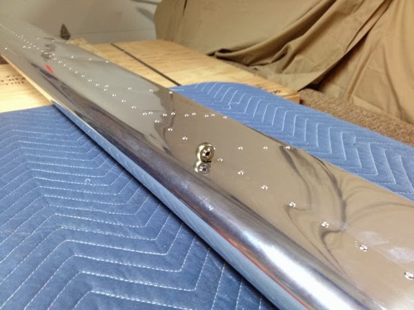
You’ve already seen the picture of the middle skin, so this picture is just a quickie of the stall warning switch access cover.  The only wrinkle here is when I went to get the screws, I only found 4 of them.  I’ve ordered the balance from Van’s because I’m not sure of the actual material/coating of replacements from the local hardware store.

IMG 2887

Stall Warning Switch Access Plate