Saturday, July 6, 2013

major setback #1

Well, it really felt good to finish the vertical stabilizer. All I had to do was bolt the upper hinge assembly to the back of the rear spar and I would be done with my first complete part—the Vertical Stabilizer.   Unfortunately,  I had a sinking feeling because the inside of those nut plates looked a bit small.   I spent some time with good lighting and some calipers and confirmed that I had made a mistake by assuming that a K1000-3 was smaller than a K1000-4.  Damn.  I think I really screwed up by installing -4's inside the assembly instead of -3's.

from a posting on Van's Airforce

I am just going by memory. If I am wrong, someone will correct me.
3 stands for 3 sixteenths or #10 screw
4 stands for 4 sixteenths or 1/4"
6 stands for #6 screw
8 stands for #8 screw
A 1 in the hundreds place means the nutplate is designed for dimpled skin.
Joe


I'll be damned if I can find any straight answers for the sizing information on these nut plates.  As near as I can find, a -3 implies that it will accept a 10-32 screw.  Great.    Now what?

From http://www.mcfeelys.com/tech/dimensions.htm we learn  ("A"=diameter of screw, "B" = diam of head, "C" = height of pan head)

Decimal Dimensions
  “A” Flat and Pan “B” Flat Head “B” Pan Head “C” Pan Head
Size MaxMin MaxMin MaxMin MaxMin
6-32 .137.131 .279.244 .270.256 .097.087
8-32 .163.157 .332.292 .322.306 .115.105
10-24 .189.181 .385.340 .373.357 .133.122
10-32 .189.183 .385.340 .378.357 .133.122
1/4-20 .249.236 .507.452 .492.473 .175.162

To convert the decimal dimensions shown above to fractional dimensions, simply multiply by 64. The result will be the number of 64ths of an inch equal to the decimal dimension. For instance, the thread size on a 1/4-20 screw is given as .249". Converting to a fraction, multiply by 64 (.249 x 64 = 15.936). The answer, 15.936, rounds to 16/64, or 1/4 of an inch.


Corresponding Fractional Measurements
  “A” Flat Head “A” Pan Head “A” Round Washer Head “A” Truss Head
Size Approx. Dia Approx. Dia T maxApprox. Dia T maxMaxMin
4 7/32 7/32 3/32N/A N/AN/AN/A
6 9/32 17/64 7/64N/A 3/3221/645/16
8 21/64 21/64 1/83/8 7/3225/6423/64
10 25/64 3/8 9/647/16 N/AN/AN/A
12 7/16 27/64 5/32N/A N/AN/AN/A
14 1/2 31/64 11/64N/A N/AN/AN/A

With that bit of information, I can finally figure out that a 10-32 is 12/64" = 6/32" = 3/16"


small   K1000-3 ?      = 3/16 = 6/32
medium  K1000-4      = 4/16 = 8/32 
large   K1000-06    = 9/32 = 9/32

Now, I'm still confused.  These are the 3 sizes of nut plates in my kit.  I selected the smallest one because it was what I thought went with -3.  This appears to be the case, but the -3 clearly doesn't fit then AN3 bolt. 

IMG 0020 2


If I have to re-work this thing, here's the instruction sheet I made for myself.  (1-3 are unrelated  and are going to be done for QC.)

V-stab re-work:

1) remove Fwd Skin from VS Assy
2) smooth top edge of all residual excess material
3) break rear/lower edges inward
 
4) drill out rivets connecting VS rear spar to 
top rib, 
mid rib, 
upper main rib, 
lower main rib,
both edges of main skin
5) remove VS Rear Spar
6) drill out rivets connecting Lower Main Spar from Main Skin
7) remove Lower Main Spar
8) drill out rivets to remove incorrect nut plates from Upper Spar Cap 
9) replace with correct (K1000-3) nut plates
10) attach Upper Hinge Assy to VS Rear Spar / Upper Spar Cap !
11) re-rivet Rear Spar to Main Skins & all Ribs
 
10) drill out rivets to remove incorrect nut plates from lower edge of front spar
11) replace with correct (K1000-3) nut plates 
 
12) replace Fwd Skin Assy onto Main Skin
refer to this assembly as Vertical Stabilizer

Friday, July 5, 2013

06-06, vertical stab skin preparation

Fairly straightforward to prep the skins with dimpling and installation of nut-plates.  There was a moderate amount of excess material to remove from the front piece, and I think that it was left on as a side effect of the cutting & folding process at the factory.  The main skin had a tiny ~2"x2" tag left on and I simply don't understand why it would have been left on.  Maybe someday I'll talk with someone who is more conversant with metal working and get some info.


IMG 2477

Tuesday, July 2, 2013

06-05, Vert Stab Skeleton Assembly

I made much more progress than expected today.  The first few days of building were pretty much monomaniacal, and I ignored household chores & stuff.  Today was 8a-5p of catching up with those things (laundry, mowing the yard, tackling a project (below), paying bills and stuff.)

The related project involved moving the dryer exhaust vent out of the garage and to an outside wall.  I suppose the original architect (or builder, in case architects don't concern themselves with that level of detail) didn't want to have the vent sticking out on the front wall of the house, but the porch is pretty protected and we have a swing in front of where the vent surfaced, so I think it will be all right.   The reason I'm even mentioning this (aside from wanting to get rid of a source of hot moist air) was that I hate making cuts and drilling holes into expensive things.  You know, houses, airplane parts…   This project (RV-12) is allowing me to learn that I really can do things with my hands and create (or at least assemble) stuff that is important and meaningful. 

Anyway, back to tonight's documentation.  Here is the V-stab skeleton.  It was quite tricky figuring out how to rivet the nut plates, as there is not much room to get the squeezer in there.  I did eventually figure it out, but I did have to drill out another rivet; this time on a partially completed, flimsy and delicate assembly.  I did it anyway!


IMG 0015 2


Monday, July 1, 2013

06-04, vertical stab spars

Nut plates have been added to the rear and front spars.  I had my first opportunity to drill out a rivet.  Turns out the rivet wasn't bad, it just wasn't attaching anything together.  Somehow, I had bumped a clecoed nut plate such that the rivet didn't go through the hole and when I set the rivet, the nut plate simply fell off.  Drilling it out wasn't too bad, but I dread the process when I have a partial airframe to navigate instead of easy-to-move bench-sized parts to play with.   Can you tell which rivet was re-worked?

IMG 0014 2

06-03, rudder spar cap preparation

It's a bit hard to make out, but there is the vertical stabilizer spar and the upper and lower end caps, all drilled and deburred. 

IMG 0013 2

06-02, rudder hinges

With great fanfare, I present to you the first assembled components of RV-12-0760!

IMG 0012

I'm going follow ng to the advice (example) of DG—a local builder who let me drool over his -12—and just make the title refer to the page number of parts/steps that I have completed.  This will save me from trying to come up with snappy titles on a regular basis and should facilitate anyone who wants to look at how I did a certain part.

I've already started on 06-03, and it's much more challenging.  I'm pretty sure Van decided that making the hinge assemblies was a great ice-breaker or confidence builder!

Project #2

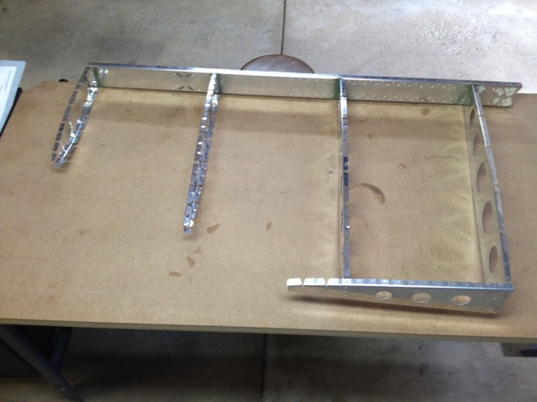
I spent 2 days working on project #2, a section of airfoil provided by Van's as a training project.  Nick spent some time with me in the shop, but he's not quite as fanatic about this as I am. :0)     I think I put about 10-12 hours total into this, much of which was the 'now what do I do to fix that?' mode.   Like the toolbox project, this required several modifications to achieve my goals of learning techniques appropriate to the RV-12.  (I think that this is an aileron section from an earlier design.)   The plans call out for driving rivets in awkward locations, including spaces that are too tight and some that are too far from an edge to use a squeezer.  It also called out double flush rivets for the trailing edge and for me to roll the leading edges.

The plans (1 sheet) reminded me to go back and re-read sections from Chap 5 to get details on those little details, but my version (RV-12) has had Chap 5 conveniently revised to state "these techniques are not applicable for the RV-12".  In other words, I was on my own.   

All in all, it's not bad.  There are several rivets that I would drill out and replace, but the kit did not have any spares of the type of pop-rivet used in the leading edge.  The double flush rivets on the trailing edge were tricky, but that's exactly why I went ahead and worked on them anyway; they don't look terribly pretty, but they are flush to the feel.  I was pleased with the fact that I came up with a way of using a squeezer; I took a 1" section of AEX-Wedge from the kit and taped backwards it over the tail of the rivet; the sandwich of sheet-wedge-sheet-reversed wedge made a parallel surface for the squeezer to work with.  Not too bad for a kludge job.  The other major 'huh, what do I do now" moment was dealing with the rivets at the trailing edges of the ribs:  no way to get a squeezer in there, so I used LP4-3 pop rivets instead.  Well, I did on one side.  The 1st rivet prevented the 2nd from fitting in until I spent many noisy minutes with a Dremel tool to cut down the 1st pulled rivet in order to make room for the 2nd. (N.B., Not an acceptable technique for a flying bird; strictly for demo work only.)

update 12/27/13:   I have since learned that the technique to deal with the inadequate clearance is to pull the 1st rivet normally, insert the opposite rivet and apply inward pressure as you slowly pull the stem.  The second rivet shortens enough to clear #1 and then sets normally.

IMG 0007 2

Work in progress.


IMG 0008 2

Finished project #2