Showing posts with label Empennage. Show all posts

Wednesday, July 15, 2015

32-12 Rudder Links

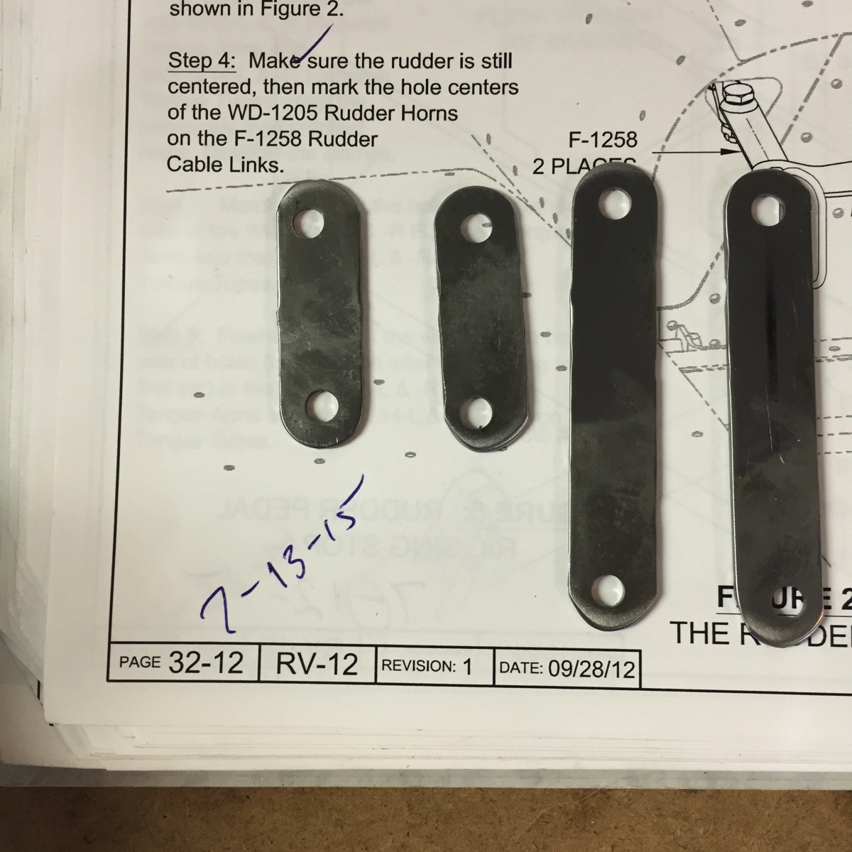
The installation process is kind of interesting.  There are links that are used to accommodate the difference in fore/aft placement of the left vs right rudder pedal horns and also to allow pivoting at the horns..  Measuring and manipulating the links inside the tunnel would be impossible.   They cleverly had me attach the cables at the front, then do all of the measuring and cutting at the tail, then move the newly fabricated links up to the tunnel.  


IMG 4529

Rudder Links

Tuesday, July 14, 2015

32-11 Running rudder cables

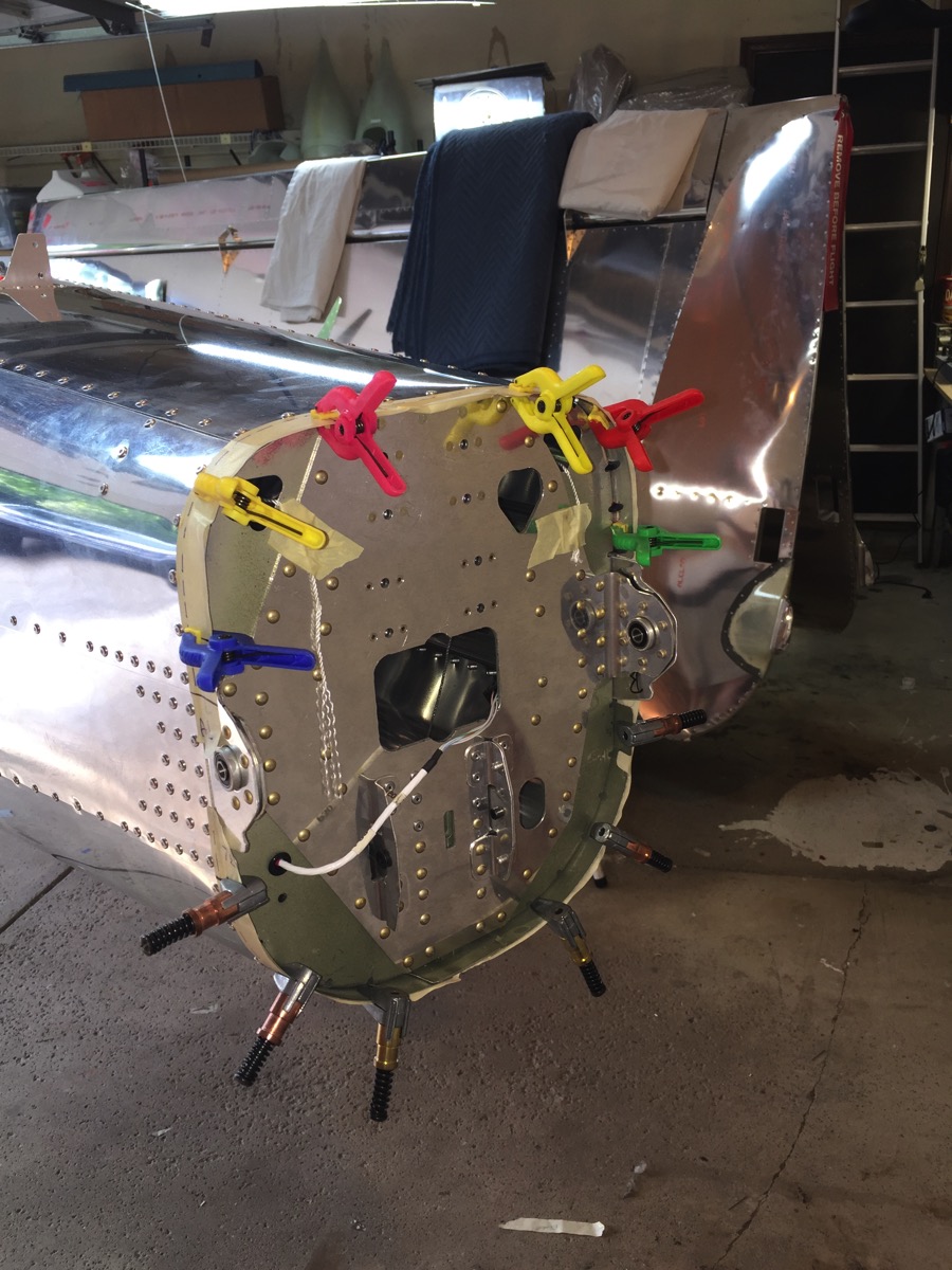
Look at the top right corner of the tail cone and you’ll see a nut w/ bolt protruding from the rear bulkhead (and pinned with a surplus long bolt to prevent it from falling back in the fuselage.)  Lots and lots of creative engineering required to get those cables back there after the original strings fell out or broke on the initial pull.  Anyway, at this point, the cables have been strung.


IMG 4527

Rudder Cables strung to rear bulkhead.

12-11 Rear Fairing final attach

This is a pretty worthless page.  It basically tells you which screws you needed to use on the preceding page.  BTW, upon fitting the fairing, the next thing I did was take it off so I could work on the rigging.

12-10 Fairing final fitting

Trimming, cutting, sanding, fitting, cursing, repeating.  I’m starting to get the hang of fiberglass work!  This page was actually pretty tough.  There are 12 nut plates arcing around the metal portion of the tail.  I discovered that if you are not perfectly lined up with the nut plate, it’s extremely easy to get cross threaded.  Once cross threaded, you are pretty much screwed.  I sheared two screws and needed to drill out and replace those nut plates, and I damaged one to the point that I knew that I would eventually repeat the cross thread event and would have to replace it... ...so I went ahead and replaced it now.  there are four very shallow indentations in the inner surface of the H stab to provide the required 1/8” clearance over the screw heads.  I also learned that it’s best to just start the 12 perimeter screws, tighten the 8 screws that hold the upper to lower ‘halves’ together, then tighten up the perimeter.  Lastly, the push rod for the AST leans a bit to the right, so I ended up widening the slot to the right to accommodate. 


IMG 4519

Rear Fairing, forward view


IMG 4518

Rear Fairing, aft view

Wednesday, July 1, 2015

12-09 Fairing initial attach

Pretty straightforward work today, which was good because I was pretty tired after working a 15 hour shift then only getting 4 hrs of sleep.  The hardest part was reattaching the h-stab by myself.  It’s currently attached only with the AN4 bolts, as I know that it’s coming off in a few days and putting those washers in is going to be a real challenge.

The fairings were drilled #40, then enlarged to #27 using the modified drill bit.  I didn’t feel comfortable using the modified bit to go through the aluminum.  I put the modified bit in on drill and a regular one on my other drill.  I could go through the fiberglass and then sequenced through with the other drill, then put in the larger cleco.

There is a tiny bit of rubbing of surface screws, so I filed a tiny amount off of the inside of the H-stab.  That will need to be rechecked a few more times to get the 1/8” required clearance.


IMG 4475

Fairing—initial attachment

Wednesday, June 17, 2015

12-06 Fairing Prep

The part that I don’t like about fiberglass work is cutting & sanding to the scribe line.  I don’t know what process Van’s uses for making the scribe lines on the pieces, but it surely one of the most subtle and difficult to see lines that I could imagine.

The Book tells me to cut a fairly simple top portion and a more complex lower portion out of a “C” shaped piece and a complete cone, respectively.  I did so.  Then I started the long & tedious (and moderately nerve wracking, in case of an excessive initial cut) process of mating the two resulting pieces to have a close fit along several edges.   I then had an idea that I think will work out well in the end.   Recall that one of the pieces was a complete cone.  that means that it contains all of the material of the “C” shaped   I took the top piece and put it on the discarded material from the lower cone stock and traced out the appropriate line.  

The 1st photo shows this stage.  Back Left is the lower part of the fairing.  Back Right is the discard from the top.  Front Right is the original top piece that doesn’t quite fit the lower.  Front Left is the discard piece from the bottom (originally, a full cone) with the top traced out.   I should mention that I don’t use shears to do my initial rough cuts prior to sanding.  I have always used a dremel tool with a narrow cutting wheel.   My insight was that I could trace out the top onto the discard portion from the bottom, then cut that out using the dremel.  The resulting new top would be a very close fit to the bottom, since they were originally a single piece.


IMG 4383

Fairing pieces


Photo 2 shows the scrap after both the bottom and the top have been cut away with the dremel tool. 

IMG 4385fiberglass scrap after cutting fairings


The 3rd photo shows the top & bottom fairings clamped into position on the tail.  There was minimal sanding needed of the adjoining surfaces.  The kerf of the dremel tool will be adequate for the gap specified by the book for paint thickness and the fit is a good as one could ask.


IMG 4384

Tail Fairing clamped onto tail

12-05 tail cone prep for fairing

Nearly 2 years ago I came up on this chapter and was disappointed, yet oddly relieved, that I couldn’t progress any further.  The kit has the fairings included in the Finish Kit shipment, yet the instructions are part of the empennage.  That was disappointing.  The relief was that I didn’t have to work with fiberglass, which at the time was a scary proposition.  Over the last many months, I’ve read and re-read the instructions without really understanding what they were telling me to do.  Finally, as is often the case, understanding comes with doing.  The whole thing about the tape is simply to get measurements onto the tail cone as to where I will later drill attachment holes.  Sigh.  The picture shows masking tape around the tail, decorated with clamps at the 12 locations that will later be drilled.  Wisely, I elected to not drill the holes now.  Reading ahead, I see that there will be some fine tuning and moving of the fairing to ensure clearance of all of the tail feathers.  Only when that’s accomplished do the holes get drilled.


IMG 4381

tail cone with measuring tape applied

Monday, June 15, 2015

11-09 AST / Trim attach

The trim assembly attaches to the anti-servo tab (commonly referred to as the trim tab, which I will often do.)  The only thing I needed to verify here was that the gap between the push rod and the skin of the stabilator itself maintained a minimum of 1/4”.  It does.  Barely.  Exactly.


IMG 4359

Stick UP, trim DOWN —maximum clearance


IMG 4358

Stick DOWN, trim UP — minimum clearance

11-08 Trim Motor Assembly attach

The trim motor can now be mounted for operational testing.  Again, nothing was tightened to airworthy condition.  I put power to the trim motor for the first time and was very relieved to see that it worked as advertised.  On the other hand, I realized that I had wired one of the connectors backwards and the pins/sockets don’t line up all that well.  I can’t figure out how to remove the pins, even with the supplied tool, so I ordered a new connector and pins and wild just amputate the incorrect connector and install new.  That will also be the time where I make the final determination of which wire is +12v = UP and which is +12v = DOWN.


IMG 4355


11-03 Horizontal Stab attach

I rearranged the garage a few weeks ago to make room for the horizontal stab.  I know it will only be attached for a few days, but I wanted to ensure that it fit correctly before going any further.  I didn’t have anyone to help maneuver the piece, so I got creative.  I picked up some adjustable work support last year.  One on each side of the stab made a good working surface that could be elevated to the proper height as the back end of the tail cone.  The tail cone has been in a wooden cradle since last year and that cradle is on wheels, so I just inched the cradle back into position until I could get the AN4 bolts in place.  I didn’t tighten things down since this was just a temporary installation, but nonetheless, it looks good!

IMG 4351

Horizontal Stabilator in position

Tuesday, February 17, 2015

11-10 V-stab forward fairing (the Nose)

Really?  An entire page to tell me to put the nose on the v-stab?  OK, I’ll post it.

IMG 4038

Forward Skin on V-stab

11-02 Install V-stab & Rudder

Another big change for the eye—the fuselage has its first tail feather installed.  Putting on the v-stab wasn’t too bad, just some bolts and screws.  Hanging the rudder could have been easy, if I just wanted a temporary installation so I could trim up the fairings, but no, that’s not my style.  I probably spent an hour trying to align the various washers while threading a bolt through the various pieces.  There’s a pretty good chance I’ll have to remove the rudder, but now I can document that I finished page 11-02, even if I have to remove the rudder in the future.

IMG 4036

V-Stab & Rudder installed

By the way, if you are wondering why the top looks weird, it’s because I have already riveted the rudder fairing in place.  The Book says to install the rudder prior to finishing the stab fairing, then to remove the rudder and rivet on its fairing.  (You can’t rivet it in place as there’s a rivet on the front and you probably can’t get a rivet puller in there.) As mentioned above, I’d like to leave this on until it gets painted.

12-02 V-stab & Rudder Fairings

I dilly-dallied for nearly 2 years before tackling the finishing steps of the vertical pieces because I had never worked with fiberglass before and I was afraid to start.  After sanding the engine cooling shroud, I realized that I had crossed a barrier and so went way back to the empennage to do a little catch up work.  (BTW, I’m still not looking forward to learning how to work wet fiberglass by myself.)   A few hours with my belt sander made fast work of sanding off the excess fiberglass and getting things close to final.  I also (re)learned to put sheets over my project to keep the dust down some!

When I got my tutorage from Rick, he was pretty even minded about the scotchbrite wheel vs a belt sander, but I’ve developed a distinct preference for the wheel, at least until now.  Now, I prefer the wheel for aluminum, but the sander is very very versatile with sanding/shaping fiberglass!


IMG 4028 V-stabilizer and Rudder Fairings 

Friday, September 27, 2013

11-04 attachment of Trim Tabs (Anti Servo Tabs)

It's still amazing to me (not in a good way) how a simple, straight-forward job can evolve into a 2 hour ordeal and then have a less-than-desired outcome.  I decided that I had to do *something* so I chose to put the ASTs on the stabilator.  First, I cut one of the hinge pins too long.  OK, that was fixable.  Cutting that steel is much harder than the aluminum, but I managed to get it done after changing the blade on the bandsaw.  OK, got the hinge pins made.

Threading the pins requires that they be perfectly aligned, which wouldn't be a problem except for the opposite AST hinge is in the way.  Yes, that little deviation makes a difference.  When I finally got the 2nd pin in place, I couldn't rotate the bent portion to be down so it could be safetied.  I had to remove the 1st hinge (Left — for some reason it's a bit easier to install than the right) install the R hinge, and then re-install the Left.    Getting the safety wire pliers to latch required using a pair of pliers to squeeze it enough to latch.  I ended up safety tying on the outside, instead of the inside, of the stabilator.  (Not as pretty.)

Lastly, when I put the bolt through the ears of the ASTs, I discovered that there's about an 1/8"th difference in the trailing edges.  I think that the fix will be to remove the 8-32 bolt and hold the edges exactly even to each other and match drill a #10 hole instead.   I'm not going to do that now.  It's 1:30 PM, but that's my equivalent of 1:30 AM!  I'll send this, and a few other less-than-inspiring photos to Rick and get his feedback.

On the other hand, it feels good to make some progress.  It's very curious, but I found that I was avoiding even this simple page while I was in waiting-limbo regarding the wing kit.  Now that I know it's in progress, I'm all gung-ho to get going again.


Horizontal stabilator with AST surfaces in place. IMG 2663


View from aft looking forward.  Note the 1/8" discrepancy between the trailing edges of the ASTs.

IMG 2667

Monday, September 16, 2013

11-08 Trim Servo Actuator assembly

I completed the trim/servo actuator assembly and mounted it just long enough to get pictures to prove it.  I took it off the tail cone and stored it inside the front of the tail cone in order to prevent it from getting bent, bashed, broken or bruised hanging out the in the air all alone.  I expect it will be about a year before I get the feathers attached and that pushrod will certainly get broken if it's attached to the tail.


IMG 0080 2


IMG 0079 2

11-06 & 07 Trim Servo bracket assembly

Not only am I waiting for wings, I also was waiting for the teflon bushings, as I had ruined 2 of them on an earlier step.  They arrived today and I had a good birthday in the garage building up the AHARS bracket and and activator assembly.

IMG 0078 2

Tuesday, September 3, 2013

11-05 Trim Servo bracket prep

Although I have no wings, I did do some minor parts that don't require attachment to the tail feathers.  I forgot to take pictures of the parts, so I just pictured the page.


IMG 0081 2

10-11, top skin. Tailcone Completed

Fairly straight forward application of the top skin and forward attach rib for the vertical stabilizer.  It's almost anti-climatic as this step is the final step for the completion of a big, visible part—the tail cone.

Side view of tail cone

IMG 0067 2


close up of the forward skin rib for the vertical stab.  It's amazing how dimpling and riveting felt routine instead of nerve wracking.

IMG 0063 2


I think this is kind of cool.  The internal reflections from the smooth aluminum make it look like there are lots and lots of internal frames, but there are actually only 3.  You can see some of the internal plumbing on the floor:  taped strings that are looped through the rudder and stabiliator cut outs, and the trim motor wires and aft pitot line coiled up on the lower right side of the picture.  It's very hard to see, but the static line and pitot line are hanging from the middle of the forward frame.

IMG 0066 2

This is a bit easier to see the pitot and static lines.  You can also see the attachment plate sticking up from the aft frame, through the top skin.  Note the brass cleco on the inside of the skin.  I elected to place a cleco in the forward-most holes of the skins to keep them from flapping around, but I didn't like the look of the clecos on the otherwise finished tail cone, so I put them inside out of sight.

IMG 0064

Thursday, August 29, 2013

10-10, upper skins


I ended up loosing 3 hours of time when I got confused on my schedule and thought I had to go to work on the 27th.  I got dressed, drove an hour only to find that I was a day early, then drove another hour home.  I made good use of the remaining time and finished attaching the upper skins.   The right side is completely riveted in this photo, but I thought that the warty clecos and ratty blue vinyl made an interesting "before" picture of the L side.  

The cradle works very well, and made it very easy to move the work piece around in the shop as I pulled lots and lots of rivets.  I'm fairly sure I will defer attaching the tail feathers because of space issues.  It's going to be at least a year (or two) before this project is ready to fly and the probability of 'hanger rash' is pretty good if I have a big 8' horizontal stab taking up garage space.  I'll make good use of the cradle and may even move it and the tail cone into the living room and keep company with the tail feathers.

Before:

IMG 2625


After:

IMG 2628

10-09, static system

Installed the static ports without too much difficulty.  The instructions call for a particular pulled rivet that you then remove the remnant mandrel and end up with a hollow hole in the wall.  I used a C-clamp and socket to gently drive out the mandrel on the R side as I have an extreme allergy to using any kind of hammer on my airplane!  The technique didn't work as well on the L because the mandrel stem I was trying to use a driver wouldn't stay centered so I held my breath and drilled it out with my trusty #52 drill bit.  No problem.  The picture is of the 1st port I installed.


IMG 2624