Saturday, October 19, 2013

14-02, Stub Spar Prep

Oct 18.  Did some work on the stub spars, but haven't finished a page yet, so this is only a partial posting without pictures.  I followed the instructions (step #3) to machine countersink both sides of the inside part of the stub spars to accept a 426AN3-3 rivet.  When I squeezed the first one, I didn't like the look of the shop side.  The countersink was too big to be filled by the metal from the tail (shop head) of the double flush squeeze.  I left that one in place, but promptly switched up to 426AN3-3.5's for the other 5 rivets.  The longer tail filled the countersink void much better.  I get off work in 2 hours and will probably work on the other countersinks along the flange edges (step #2) and finish off the stub spar prep later today.  

10-21.  Finished the small parts and stub spar prep work with Nick.  Mostly pretty straightforward, but I’m not entirely happy about the hinge assemblies.  When I squeezed the flush rivets next to the bearing, the edges flared out a bit.  I’m not sure what pattern of squeezing the rivets would have minimized this, but I didn’t use that pattern :(

You can see the slight gap as you look down the edge of the hinge assembly (by itself and more so on the one on the right.)  I’ll put these in my “hall of shame” photos for later review by Rick Grey. 

IMG 0096 2

IMG 0095 2


IMG 0094 2

The stub spars look nice.  I fretted a bit about why I was countersinking them and went so far as to post to VAF.  The answer was remarkably straightforward:  Van’s has already dimpled the appropriate sheet metal for me.

IMG 0097 2


On to page 14-03!

Monday, October 14, 2013

13-03, Rib Attach Angles

Fairly straightforward day.  Riveted attach angles onto the spars for later attachment of ribs.  No errors per se, but a lot of final drilling of holes that are supposedly final size from the factory.  There was no way that roughly half of the holes in the spars were going to accept the LP4-3 until drilled out with a #30 bit.

I did decide to use plain sawhorses to work with the spars for now.  I will still need to construct the wing dolly, as the sawhorses are OK for working with two spars, but would only support (store) 1 wing, and that's neither safe nor space efficient.

Rib attach angles on the outside edges of the spars.

IMG 0093 2

Rivets placed near roots of spars.

IMG 0094 2

Saturday, October 12, 2013

13-02, small parts prep, Tie Downs

Well, it certainly was fun jumping in and getting to work on the wings.  That is, until I found my first blunder.

Look at the photo below. You are seeing the L upper wing tie down (tie up?).  The photo shows the effect of not establishing a good bore-sight down the predrilled hole.  I was actually at a 6° angle and drilled through the surface of the aluminum extrusion.  Unfortunately, I was not looking at the extrusion itself, as I had turned the spar over to improve access.  (I don't know if watching it would have made much difference, but I probably would have caught it earlier and been able to re-align the drill.)  The tap has been re-inserted for this photo and is just barely visible at the lower end of the hole.


IMG 0086 2

The photo below shows the 6° up angle relative to the spar surface.  (iPhones make great general purpose tools:  the current iOS has an excellent inclinometer.)

So far, I have identified 3 paths to pursue.  Easiest (and therefore of greatest suspicion) is to ignore it and use the tie down as if nothing happened.  The threads are intact along the upper (as oriented in the photo) and lateral walls of the long axial hole, but probably non-existent on the lower edge of the hole directly under the unwanted opening.  As a total WAG, I guess that there's a 30° arc x 1/2" where there are no threads.  Is that lack of contact enough to compromise the strength of that bolt?  (What is the function of that bolt, anyway?  I'm further guessing that its to suspend the wing in maintenance actions.)

2nd option is to ignore it completely. That is to say mark the tie-down as InOp and never use it.

3rd option is to re-drill with a larger bit and re-tap with larger threads.  To ensure good strength, I would tap 2" to obtain a full inch (original spec) of completely engaged threads.  Will there be sufficient aluminum to accept the larger bolt?  Hmm.  Sounds like I need an engineer. 

IMG 0087 2


On the other hand, I did get some useful things done correctly.  As is typical for the first few pages of a chapter, it was a lot of separating and preparing small parts.  Fun, mindless, productive:  all in all a good day.  (Learning how to repair mistakes is part of the goal of this project, eh? :0)


Here are the various attach angles (W-1206V x20, W-1206T x2) and the assymetric rib doublers.

IMG 0088 2

Not easy to see, but there are the match drilled holes on the L spar.

IMG 0090 2

Here are the properly drilled & tapped tie downs :-)

IMG 0089 2

Wing Kit Arrived!

Hurrah!  I can get back to work.  The wing kit arrived, only about a month behind their original prediction.  (I'm currently overwhelmed at work myself, so I'm not complaining.  Much.  Every company should be so blessed as to be running behind production schedule :0)

IMG 2686


IMG 2687

A solid day of work in the garage has resulted in the crates being opened, broken down and/or stored for future use, all components removed, stored and inventoried.  I found one discrepancy,  no A-1210B-L (Middle Nose Skin), but two -R's instead. I've already sent my email to Van's.  There's no rush, I don't think I'll need that part for quite some time.  

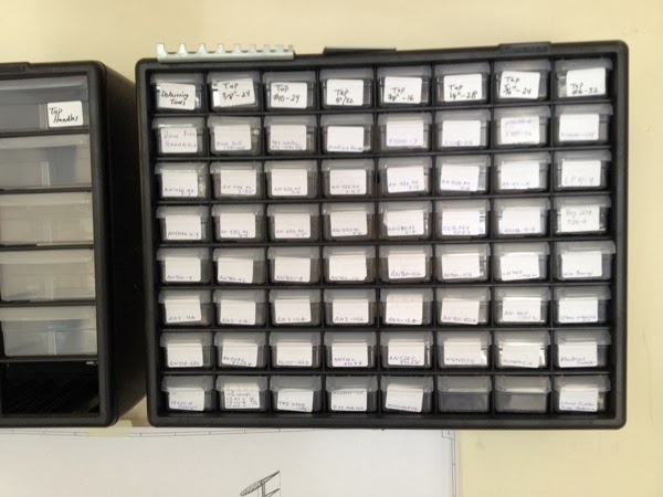
I also took the time to overhaul my bins-of-small-parts and followed the advice of making an individual bin for each type of part, not a bin for each bag of parts.

IMG 0084 2

I have 3 hours before I need to get ready for work (again).  I might go play in the garage, I might go out to the airport and get some flight time in the Cardinal.  I will try to engage Nicholas and get him involved in anything, so that will probably be the determining factor.

Friday, October 11, 2013

Fuselage & Finish Kits ordered

Financing is proceeding (I think.)  I got a copy of the Certificate of Insurance for $40K of builder's coverage in favor of First Pryority Bank.  I have requested that they forward $5000 to Van's as the down payment for both of those kits.  Financing is proceeding (I think.)  I got a copy of the Certificate of Insurance for $40K of builder's coverage in favor of First Pryority Bank.  (I had originally assumed that the COI was sent to the bank when I revived my bill for same.  My bad.)

I've heard that the fuselage kit has a longer lead time than the other kits, so I'm hedging my bet that the finish kit may be ready earlier and I can find something to do (e.g., tail-cone fairings) should it arrive before the fuselage kit.

Wednesday, October 2, 2013

Wing Kit Shipped !

"David, your RV-12 wing kit is shipping today thru Old Dominion Freight Lines 
under tracking #77740463490.  You can track the shipment anytime after 
today thru their website at odfl.com.  They will call you to arrange the 
delivery which is collect upon arrival.  The freight costs are approximately 
$370 or so.  Thank you for your patience in waiting for this shipment.  Have 
fun building:)  Barb"


I have great news on the financial front, too.  Although I've been approved for a builder's loan from NAFCO, I also came across a referral to a tiny bank in Pryor, OK.  Their former CFO is an avid pilot and he's very proactive for loaning money to GA pilots, including RV kit builders.  I was approved in about 3 hours.  This great news will let me decouple building from purchasing, thus removing one more headache. :0)

Friday, September 27, 2013

11-04 attachment of Trim Tabs (Anti Servo Tabs)

It's still amazing to me (not in a good way) how a simple, straight-forward job can evolve into a 2 hour ordeal and then have a less-than-desired outcome.  I decided that I had to do *something* so I chose to put the ASTs on the stabilator.  First, I cut one of the hinge pins too long.  OK, that was fixable.  Cutting that steel is much harder than the aluminum, but I managed to get it done after changing the blade on the bandsaw.  OK, got the hinge pins made.

Threading the pins requires that they be perfectly aligned, which wouldn't be a problem except for the opposite AST hinge is in the way.  Yes, that little deviation makes a difference.  When I finally got the 2nd pin in place, I couldn't rotate the bent portion to be down so it could be safetied.  I had to remove the 1st hinge (Left — for some reason it's a bit easier to install than the right) install the R hinge, and then re-install the Left.    Getting the safety wire pliers to latch required using a pair of pliers to squeeze it enough to latch.  I ended up safety tying on the outside, instead of the inside, of the stabilator.  (Not as pretty.)

Lastly, when I put the bolt through the ears of the ASTs, I discovered that there's about an 1/8"th difference in the trailing edges.  I think that the fix will be to remove the 8-32 bolt and hold the edges exactly even to each other and match drill a #10 hole instead.   I'm not going to do that now.  It's 1:30 PM, but that's my equivalent of 1:30 AM!  I'll send this, and a few other less-than-inspiring photos to Rick and get his feedback.

On the other hand, it feels good to make some progress.  It's very curious, but I found that I was avoiding even this simple page while I was in waiting-limbo regarding the wing kit.  Now that I know it's in progress, I'm all gung-ho to get going again.


Horizontal stabilator with AST surfaces in place. IMG 2663


View from aft looking forward.  Note the 1/8" discrepancy between the trailing edges of the ASTs.

IMG 2667