Saturday, October 11, 2014

32-02 Brake Lines

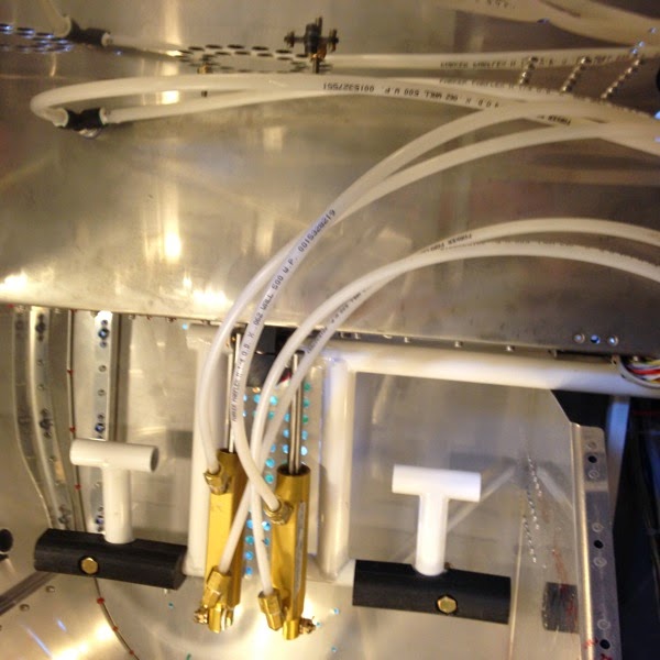
We’re into a new chapter!  Flight controls can be divided into 4 systems:  brakes, flaperons, rudder, elevator.  Of these, the 1st two can be completed within the fuselage, but the other two require the tail cone to be installed.  I’ll do what I can in front.  

IMG 3691

Brake Fluid Reservoir

IMG 3695

Brake Lines to Reservoir

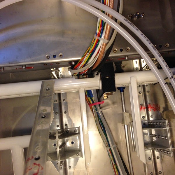
Although not pictured, I had the obligatory bit of fun with the installation of the clamp that holds the crossover brake lines in place.  I discovered that I had routed the wiring harness in front of, not behind, the brake lines.  That meant that I had to remove the brake lines from the pilot’s side and put them on the correct side of the wiring harness before I could attach their retention clamp.  Sigh... the joys of doing things for the first time...

31B-23 Aft Pitot Line, System Blocks


This was pretty straightforward.  I pulled the pitot line out of the tail cone and installed into the forward half of the plane, as per plans.  This will require me to re-install it in the tail cone, but that should be doable since it only goes back about 9-12”, to the AHARS unit in the proximal portion of the cone.  I expect it will require a contortionist, but that’s what Nick is for.  :-)


IMG 3681

 Pitot Tube & System Block


By the way.  Do you see the flaperon mixer arm?  Does it look normal to you?  Stay tuned for an update in the next day or so.  (Right now, I’m stuck at work with the schedule from hell, so I may not be able to do any work on the plane and update it for a few days.)

31B-25 Over Rudder Wireway

This guy was conceptually simple, but a royal PIA to install.  It isn’t even very visible in the picture, but if you look close you can see a metal tab (with a punched hole) under the wiring bundle and over the rudder torque tubes.  That little metal tray was inserted over the torque tubes and then held with a screw into a previously placed nut placed.  Well, trying to line up that screw into the nut plate when you can’t see either one, and can’t actually hold/touch the screw, and can’t be in two places at once...  well, you get the idea.  I got lots of creative ideas using an awl, rivet stems, flashlights and (literally) blind luck.   Got it.  Eventually.


IMG 3675

Over Rudder Wireway

Saturday, September 27, 2014

31B-22 Fuel Pump Noise Filter

IMG 3672

Fuel Pump Noise Filter (Electrical)

The electrical system has a couple of capacitors on the 12V line to filter out some electrical noise.  This guy was a bit of a challenge to place, due to the narrow space (rear tunnel, below the baggage deck), but was conceptually simple.  It’s tie-wrapped to the wiring bundle and then glued to the lower skin with RTV (the red smear). 


In case you can’t tell, I did a lot of “little things” last week.  I’m trying to catch up on all of the little detours I’ve created for myself and get back to something more-or-less by the book.  Finally deciding to divide the trim wire harness allowed me to finish up the wiring, etc.  I’ve only got 2 or 3 pages of fittings & supports, and then go through with a bunch of tie wraps to make it look all nice.  


31B-04 installing Trim wires

Another successful case of Defeat being snatched from the grasp of Victory, but then Victory coming back for the win.  I divided the trim cable and installed micro-fit pins/connectors on the new ends for later assembly when I put on the tail cone.  I pulled the aft pitot line and routed it into the cockpit per plans and will run it back into the tail cone at the appropriate time. (note that the pitot line only goes back about 12” into the tail.)  This allowed me to run the trim lines into the WH-00046 connector, pictured below.

What is not pictured below is that I misplaced one of the pins into hole #32 instead of #30.  It only took a few hours, a phone call to Van’s and then watching a 2 min video from Steinair.com on how to use the pin insertion/removal tool.  I had used such a tool many, many, many years ago when I was an electronic engineer, but the memory escaped me until I saw the video.  15 more minutes of fiddling and I got the pin out of the wrong hole and back into the correct one.   In the process, I had to destroy the nice green shrink wrap you see below.  It is now ignominiously replaced with duct tape.  :-(

IMG 3667

WH-00046 after placement of Trim Wiring Harness

34-07 Canopy Latch Handle

I actually did this page a few weeks ago, but I didn’t like the result.  I didn’t do a good job holding things in place when I drilled the handle and the latch itself.  Although everything fit together, it was a little bit off and rattled.  I know that it would rattle in flight and drive me crazy, so I ordered new pieces from Van’s and repeated the assembly last week.

Here’s the jig I used to hold the handle and the latch in a vertical plane while I drilled with the press to make the pilot and then the larger holes prior to tapping.  Below, is the finished product.  Again, I’m not in any danger of wining a Lindy with this ship, but it’s functional and safe.


IMG 3663

Canopy Latch and Latch Handle in drilling jig


IMG 3664

Canopy Latch Handle

34-09 Riveting the Canopy

Whoo-Hoo!  This is one of the milestones that I’m really pleased to reach:  the canopy is riveted onto its frame, without a significant scratch or any fracture of any sort.  For some reason, I’ve been worried that it’s a fragile thing that needs to be protected by its frame.  It might be an unreasonable fear, but I’m glad it’s behind me regardless.

I’m going to stop canopy work here—the rest is fiberglass work for the front skirt, and I have no experience with fiberglass yet.  Since that’s a very cosmetically visible component, I’ll defer that until I get some education and practice. 

IMG 3657


IMG 3658